
Rigid Carbon Felt Insulation for 8-Inch SiC PVT: Rayon vs. Pitch, Outgassing, and Thermal Drift Mitigation
Compare rigid carbon felt insulation for 8-inch SiC PVT: qualify rayon, pitch and PAN grades, outgassing and thermal drift. Build your RFQ evidence checklist.
Rigid carbon felt insulation for 8-inch SiC PVT should be selected by finished-grade evidence, not precursor name alone. Rayon-based carbon-bonded carbon fiber (CBCF) is a documented starting point. Pitch- and PAN-based candidates need the same checks: thermal conductivity under the intended atmosphere, dimensional stability, lot-specific purity, outgassing, and compatibility with the complete hot zone.
This guide helps crystal-growth engineers, furnace builders, and procurement teams turn those checks into an RFQ and qualification plan. Start with the rigid carbon felt insulation product requirements, then use the comparison and checklist below to request evidence for your reactor.
Published and reviewed: October 27, 2026. Scope: Global, English-language engineering and procurement guidance for 200 mm (8-inch) SiC physical vapor transport (PVT / seeded sublimation) hot zones. The thermal-field discussion emphasizes RF-induction systems; resistance-heated systems need their own heating model. This is a source-based qualification framework, not a report of Sicgraphite production trials. Numerical examples are identified as illustrations, and acceptance limits must come from the furnace design and substrate specification.
Qualification boundary: A precursor label, a maximum-temperature rating, or a low ash value cannot establish an acceptable growth interface or component lifetime. Compare candidate insulation in the same geometry, pressure, atmosphere, and thermal cycle before approving a substitution.
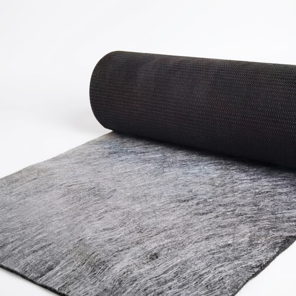
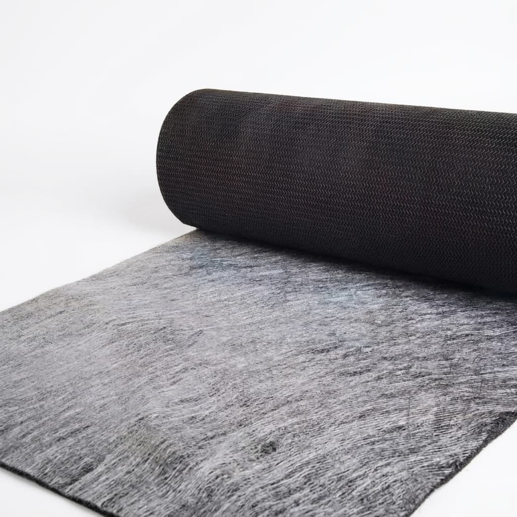
Illustrative insulation material surface; use Figure 1 for the rigid-cylinder layout. The photograph does not establish a specific grade or precursor.
1. Thermal Field Dynamics in 8-Inch SiC PVT Growth
In a PVT reactor, SiC source material inside an isostatic graphite crucible sublimes and supplies vapor species to a cooler seed. Insulation is one part of a coupled electromagnetic, heat-transfer, and growth system. Its effect must be considered together with the crucible, seed holder, source charge, and coil position.
A published 8-inch PVT thermal-field study reported reducing the modeled seed-surface temperature difference from 93 K to about 11 K by changing the seed-cavity design. Its deposition experiments support the importance of thermal-field design; they do not compare rayon and pitch felts or establish a universal insulation specification.
For an 8-inch boule, three physical phenomena dictate insulation performance:
The Dominance of Radiative Heat Transfer
Radiative exchange becomes important at PVT temperatures. For two idealized facing surfaces, net exchange depends on the difference of their absolute temperatures to the fourth power, as well as emissivity and view factors. In porous felt, fiber orientation, density, gas pressure, and radiation all affect effective thermal conductivity. A room-temperature value or a nitrogen datasheet curve cannot be treated as a low-pressure argon result.
Isotherm Curvature Control
Sidewall, lid, and base insulation affect different heat-loss paths. Changing one region can change both axial and radial gradients. Lower conductivity is therefore not automatically better: the objective is the interface shape and temperature distribution required by the validated growth recipe. Recheck the thermal model when changing thickness, density, facing, seams, or material grade.
Thermal Drift During Growth and Reuse
Shrinkage, deposits, handling damage, and changes in the insulation structure can alter heat loss over time. Track heater power alongside pyrometer readings, chamber pressure, charge configuration, and component condition. Power drift alone cannot identify felt degradation because source evolution, optical-window contamination, and other hot-zone changes can also affect the signal.
2. Precursor Chemistry: Rayon-Based vs. Pitch-Based vs. PAN-Based Rigid Felt
Rigid felt manufacturing combines carbon fibers with a carbonaceous binder and high-temperature treatment, followed by machining. Mersen's CALCARB documentation identifies a rayon-derived short-fiber structure bonded by carbonized phenolic resin. SGL's rigid-felt documentation describes fiber/binder processing and optional graphite-foil or C/C layers.
For rayon-based CBCF, request the exact finished grade and processing record rather than treating every rayon product as equivalent. For pitch-based felt, establish the fiber type and finished structure; a precursor label alone does not establish high conductivity or poor stability. For PAN-based felt, request finished-material purity and outgassing evidence rather than inferring residual nitrogen from precursor chemistry. The cited sources do not provide a controlled comparison of all three families, so no universal ranking or numerical performance ranges are assigned here.
Figure 1: Conceptual hot-zone layout, not to scale. The optional facing and illustrative isotherms show qualification interfaces, not measured temperatures or a guaranteed vapor seal.
1. Rayon-Precursor Rigid Felt (CBCF)
Rayon (regenerated cellulose) fibers possess a distinctive crenulated (irregularly serrated) cross-sectional morphology. When carbonized and graphitized:
- Low Thermal Conductivity: Even after heat treatment above 2,400°C, rayon carbon fibers maintain a disordered, non-graphitizing "turbostratic" carbon structure. Because the degree of crystalline graphitization remains low, phonon conduction along the fiber axis is inherently suppressed. This makes rayon-based CBCF the premier choice for achieving the lowest thermal conductivity at 2,000°C–2,400°C.
- Isotropic Thermal Resistance: Random short-fiber orientation ensures uniform insulation in both radial and axial directions.
- Clean Halogen Purifiability: The cellulose precursor has naturally low trace metal content, enabling deep purification down to total ash levels below 5–10 ppm.
- Limitation: Lower mechanical modulus and compressive strength compared to pitch. Requires careful handling and CNC precision machining.
2. Pitch-Precursor Rigid Felt
Pitch-based fibers are derived from petroleum or coal-tar pitch containing polyaromatic mesophase liquid crystals:
- High Modulus & Compressive Rigidity: Pitch fibers have highly aligned graphene planes along the fiber axis. The resulting rigid felt exhibits superior structural stiffness and resistance to crushing or handling damage.
- Thermal Conductivity Drawback: Pitch fibers graphitize exceptionally well. At PVT operating temperatures (2,200°C), graphitization continues, causing the thermal conductivity of pitch-based felt to rise sharply over successive runs. This thermal drift distorts calibrated growth recipes.
- Application Niche: Primarily used in heavy structural load zones or large industrial vacuum sintering furnaces where mechanical load-bearing capacity outweighs delicate thermal gradient stability.
3. PAN-Precursor Rigid Felt
Polyacrylonitrile (PAN) fibers are widely used across general high-temperature furnaces:
- Balanced Mechanical Strength: Offers high tensile and tear strength at a competitive cost point.
- Nitrogen Outgassing Risk: PAN contains significant nitrogen in its polymer backbone (acrylonitrile monomer). Unless subjected to prolonged ultra-high-temperature halogen purification (>2,400°C), PAN-based rigid felt can release trace nitrogen gas during PVT growth runs. In SiC crystal growth, nitrogen is a potent n-type dopant; uncalibrated nitrogen outgassing causes uncontrollable carrier concentration spikes in high-resistivity or semi-insulating 4H-SiC substrates.
3. Structural Comparison: Precursor Materials vs. PVT Performance
Use this table to compare supplier submissions. These are qualification questions, not measured rankings. Require the same test conditions before comparing numbers across grades.
| Selection parameter | Rayon-based CBCF | Pitch-based rigid felt | PAN-based rigid felt | Evidence needed for 8-inch PVT |
|---|---|---|---|---|
| Precursor identity | Commercial short-rayon-fiber CBCF is documented by Mersen. | Ask for the exact fiber type and grade. | Ask for the exact fiber type and grade. | Traceable grade, binder, and production route. |
| Bulk density and orientation | Compare the specified finished-grade range. | Compare the specified finished-grade range. | Compare the specified finished-grade range. | Lot density, sampling locations, and fiber orientation. |
| Thermal conductivity | A rayon label does not supply an argon conductivity curve. | Do not infer finished-felt conductivity from the fiber alone. | Do not infer finished-felt conductivity from the fiber alone. | Temperature, atmosphere, pressure, direction, uncertainty, and test method. |
| Outgassing | Confirm post-treatment and storage history. | Confirm post-treatment and storage history. | Confirm post-treatment and storage history. | Blank-corrected gas-load or residual-gas data under an agreed cycle. |
| Dimensional stability | Check the complete bonded and faced part. | Check the complete bonded and faced part. | Check the complete bonded and faced part. | Dimensions before and after representative thermal exposure. |
| Purity | Grade-specific; precursor does not guarantee trace-element limits. | Grade-specific; precursor does not guarantee trace-element limits. | Grade-specific; precursor does not guarantee trace-element limits. | Lot-specific elemental report, reporting limits, and separate ash result. |
| Facing and dust control | Qualify foil, coating, or infiltration as part of the assembly. | Qualify foil, coating, or infiltration as part of the assembly. | Qualify foil, coating, or infiltration as part of the assembly. | Facing integrity, seam design, handling cleanliness, and gas-flow effects. |
| Reuse and thermal drift | No universal number of acceptable runs. | No universal number of acceptable runs. | No universal number of acceptable runs. | Inspection records and a normalized furnace-performance trend. |
Selection rule: Shortlist a documented rayon CBCF grade when its evidence fits the application. Accept a pitch- or PAN-based alternative only after its finished-grade data and furnace trial meet the same acceptance criteria. If comparable data are missing, the result is “not yet qualified,” rather than a presumed material-family winner.
4. Key Failure Modes in 8-Inch SiC PVT Insulation
Silicon Vapor Penetration ("Siliconization")
Process vapor reaching exposed carbon can change the insulation structure; silicon reacting with carbon can form SiC. Deposits and conversion may change heat transfer and brittleness, but the conductivity change depends on the extent and location of damage. The sources below do not establish a universal percentage increase or service-life improvement.
Engineering response: Review crucible leakage paths, hot-face exposure, joints, and exhaust routing. Assess graphite foil, protective coatings, or infiltration with the supplier. SGL documents laminated facing options, and Mersen documents protective treatments. These options do not establish a hermetic seal for every assembled PVT cylinder. Check seams, ports, bonding, and possible changes to electrical coupling and gas flow.
Dimensional Shrinkage and Joint Gaps
A small dimensional change can create a significant assembly gap. Illustrative calculation: 1% axial shrinkage of a 600 mm cylinder gives a 6 mm height loss. This is geometry, not a measured shrinkage rate or a prediction of crystal yield.
Measure reference features before and after a representative exposure cycle, and compare them with the drawing's gap budget. Set allowable change from the thermal model and joint design. Ask for the actual heat-treatment history; a treatment temperature alone does not prove stability over the intended service cycle.
Fiber Dusting and Handling Damage
Machining, transport, and installation can release particles or damage edges. Specify a supplier-approved cleaning process and inspect the finished part, including ports and joint surfaces. Filtered dry inert-gas cleaning may be suitable when approved; avoid introducing shop-air oil, moisture, unqualified repair compounds, or cleaning methods that damage the porous structure. Document facing condition after unpacking and installation.
A Practical Thermal-Drift Comparison
Before approving a new grade, record a baseline with the current approved hot zone. For a candidate trial, hold the geometry, source loading, pressure, gas flow, power-control method, and measurement locations as consistent as possible. Record:
- Part dimensions, mass, lot, facing, and inspection photographs before installation.
- Pump-down and bakeout gas-load trends with an empty-furnace baseline.
- Power and temperature trends at comparable points in the cycle.
- Post-run dimensions, deposits, cracks, facing damage, and applicable crystal-quality results.
Define acceptance and replacement triggers before the trial. This workflow is a proposed qualification method, not evidence of a completed Sicgraphite test. Keep measurement uncertainty and changes in the source charge or optical path in the trial record.
5. Trace Element Purity and Acceptance Evidence
Bulk ash and elemental purity answer different questions. Ash is a residue measurement under a specified method; a GDMS report measures selected elements with method-dependent reporting limits. A GDMS elemental sum must not be presented as a total-ash test. Ask the laboratory which elements and sample forms its method can quantify, and use a separate validated gas-analysis method where needed for nitrogen or outgassing.
For context, Mersen describes purified CALCARB with impurity levels below 20 ppm. That manufacturer statement is grade-specific; it does not establish a universal SiC acceptance threshold or a Sicgraphite lot specification. The buyer must allocate limits from the intended substrate grade, contamination budget, process exposure, and measurement capability.
| Analyte or measurement | Why the buyer should review it | What to put in the RFQ |
|---|---|---|
| Boron (B) | Unintended acceptor contamination can affect compensation. | Buyer-approved limit, method, and reporting limit. |
| Aluminum (Al) | Unintended acceptor contamination can affect carrier control. | Buyer-approved limit and lot-traceable result. |
| Iron (Fe) | Metallic contamination is relevant to defect and electrical performance. | Agreed maximum, sample location, and analytical uncertainty. |
| Titanium (Ti) | Trace-metal suitability depends on the intended substrate and process. | Include in the elemental panel where the contamination budget requires it. |
| Vanadium (V) | Intentional versus unintended incorporation depends on substrate type. | State the intended electrical grade and acceptable background. |
| Nitrogen and evolved gases | Bulk composition and released gas are different measurements. | Validated methods, blank correction, and agreed thermal-cycle conditions. |
| Total ash | Screens inorganic residue but does not identify every contaminant. | Separate ash method, units, acceptance limit, and batch traceability. |
Purification verification: Request the supplier's qualified purification route, representative sampling plan, and certificate tied to the delivered production lot. The sampling location must represent the finished part, including any facing or coating. A generic brochure, a certificate from another grade, or a result below an unspecified detection limit is insufficient.
6. The 8-Point Engineering and Procurement Audit Checklist
Use this checklist to compare quotes and define the evidence needed before production approval:
- 1. Precursor and grade: Identify rayon, pitch, or PAN; record the exact finished grade, binder route, and change-control agreement.
- 2. Thermal data: Request effective conductivity over the relevant temperature range, with gas, pressure, direction, density, test method, and uncertainty. Establish a validated correlation if testing cannot reproduce the full service condition.
- 3. Dimensional stability: Agree on thermal exposure and dimensional reference points; measure radial and axial change against the assembly's gap budget.
- 4. Purity and outgassing: Obtain lot-specific elemental data and a separate ash result. Define gas-load or residual-gas acceptance criteria, including the furnace blank and measurement conditions.
- 5. Facing and joints: Qualify foil or coating adhesion, seam overlap, ports, thermal cycling, and vapor-flow paths as an assembly.
- 6. Machining and tolerances: Issue an approved OD/ID/height drawing, joint geometry, and inspection plan. Set tolerances from fit and heat-leak requirements rather than a generic machining claim.
- 7. Cleaning and handling: Agree on a compatible cleaning method, particle inspection, edge protection, and approved repair policy.
- 8. Packaging and release: Specify clean sealed packaging, lot labels, storage conditions, and re-bake criteria after exposure. Keep loose desiccant away from the component, and require formal sample approval before a production substitution.
Send the completed requirements to Sicgraphite for a grade and documentation review, including any limits for which supporting data are still missing.
7. Frequently Asked Questions (FAQ)
Q1: Why choose rigid carbon felt rather than soft graphite felt for an 8-inch PVT hot zone?
Rigid felt provides a machinable, self-supporting geometry that can help control seams and assembly dimensions. Soft felt can still be useful where conformity or layered construction is required. Select the form through the mechanical layout and thermal model; neither form guarantees crystal quality or constant dimensions over reuse.
Q2: How does rigid carbon felt interact with RF induction heating?
Carbon insulation can carry induced currents. The cited 8-inch study includes electromagnetic heating of the insulation as well as the crucible. Electrical properties, coil frequency, dimensions, facings, and deposits can affect that coupling. Include the proposed insulation assembly in the electromagnetic model rather than assuming all RF power reaches only the crucible.
Q3: How many growth runs can a rigid carbon felt cylinder survive?
There is no supported universal run count for bare or foil-faced felt. Establish replacement criteria from the validated recipe: dimensional change, cracks, facing loss, deposits, contamination results, and normalized power or temperature trends. A claim such as “15–25 runs” needs comparable operating conditions and a traceable service record before it can support a purchasing decision.
Q4: Can damaged or siliconized rigid felt be refurbished?
A minor handling defect may be repairable only if the supplier and furnace owner approve the repair material and requalification. Machining off a surface deposit does not demonstrate that the internal structure is unchanged. Quarantine parts with suspected penetration, cracking, or unacceptable drift until inspection and thermal-performance evidence support reuse.
Q5: What bakeout and outgassing procedure should be used before first production use?
Use a furnace- and grade-specific approved procedure. A universal ramp rate, vacuum level, or soak temperature cannot be inferred from the precursor. Agree with the furnace owner and material supplier on:
- The permitted heating atmosphere, ramp limits, temperature, pressure, and hold conditions.
- An empty-furnace baseline and an appropriate residual-gas or gas-load measurement setup.
- Acceptance criteria for gas species or gas load at defined measurement conditions; pump-down pressure alone is not sufficient.
- Cooldown, clean handling, storage, and repeat-bake requirements before loading a production seed.
Record the conditioning cycle with the delivered lot and repeat qualification after a material, facing, or process change that could alter gas release.
8. Conclusion: Approving Insulation for an 8-Inch PVT Hot Zone
A documented rayon CBCF grade is a practical candidate, but precursor choice is only the start. The purchasing decision should connect finished-grade thermal data, dimensional stability, purity, outgassing, and assembly condition to an approved furnace trial. Protective facings can be useful; they cannot substitute for checking joints, process exposure, and replacement criteria.
Review your hot-zone requirements with Sicgraphite. For custom rigid carbon felt insulation cylinders, discs, and hot-zone parts, prepare the drawing, operating atmosphere and pressure, temperature cycle, facing requirements, contamination budget, and qualification evidence you need. Contact the engineering team to discuss grade availability and sample qualification. Confirm achievable specifications in the quotation and lot documentation before ordering production quantities.
9. Sources and References
Sources reviewed October 27, 2026. Manufacturer information describes the named products; it is not a certificate for a Sicgraphite shipment. The research paper supports thermal-field design considerations, not a comparative felt lifetime or a universal purity standard.
- Mersen — Rigid and soft carbon insulation. Primary manufacturer documentation for CALCARB CBCF: rayon-derived short fibers, carbonized phenolic binder, high-temperature treatment, purification, and protective options. No controlled rayon/pitch/PAN comparison is supplied.
- SGL Carbon — SIGRATHERM rigid felt. Primary manufacturer description of carbon-fiber/binder processing, machining, and optional graphite-foil or C/C lamination. This page does not establish the elemental limits or PVT service life of the article's candidate parts.
- Materials 2023, 16(2), 767 — Design and Optimization of Thermal Field for PVT Method 8-Inch SiC Crystal Growth. Original thermal modeling and deposition study; see the abstract, conclusions, and material-model tables. DOI: 10.3390/ma16020767. Its geometry and operating conditions limit direct transfer to another furnace.
Author

More Posts
Preventing Wafer Slip and Bow in 200mm SiC Epitaxy: Susceptor Specifications
A comprehensive engineering and procurement guide to mitigating wafer slip, bow, and warp in 200mm SiC epitaxy through advanced SiC coated graphite susceptor design.

Graphite Heating Elements in High-Temperature Vacuum Furnaces: Meander vs. Cage Geometry, Arcing Prevention, and Creep Resistance
Compare graphite heating elements for vacuum furnaces: meander vs. cage, arcing risks, creep, and terminal design. Build your RFQ with an acceptance checklist.
C/C Composite Fasteners vs. Molybdenum in Vacuum High-Temperature Furnaces
A technical comparison of Carbon/Carbon composites and Molybdenum hardware in vacuum furnaces. Discover why C/C composites are replacing refractory metals.