SiC GraphiteSiC Graphite
Start inquiry
SiC GraphiteSiC Graphite
WhatsApp
SiC GraphiteSiC Graphite

China-based industrial OEM supplier supporting customization, quality control, and global delivery.

Inquiry Email

[email protected]

Email app

Include process, product type, drawing status, purity/coating target, dimensions, quantity forecast, operating conditions, and delivery date.

Instant Chat

+8618857971991

Chat on WhatsApp

Best for quick drawing checks, process fit questions, and RFQ clarification.

Products
  • SiC Crystal Growth Crucible
  • High-Purity Graphite Heater
  • Graphite Hot Zone
  • Rigid Carbon Felt Insulation
  • CVD SiC Coated Susceptor
  • SiC Coated Wafer Carrier
  • SiC Coated Dummy Wafer
  • C/C Composite Fasteners
  • C/C Composite Trays
  • Vacuum Pump Graphite Vanes
  • Aluminum Degassing Graphite Rotor
  • TaC Coated Graphite Crucible
  • Tantalum Carbide Guide Ring
  • TaC Coated Susceptor
Solutions
  • SiC PVT Crystal Growth
  • MOCVD & Epitaxy
  • Semiconductor Thermal Field
  • Vacuum Furnace Hot Zone
  • High-Temperature Carbon Composites
  • Industrial Graphite Replacement
OEM Capabilities
  • High-Purity Graphite Machining
  • CVD SiC Coating
  • C/C Composite Fabrication
  • Purity and Ash Control
  • Drawing-Based Custom Parts
  • Inspection and Export Packaging
Resources
  • Blog
  • About
  • Contact / RFQ
  • Quality & Metrology
  • OEM Compatibility Matrix
  • Privacy Policy
  • Terms of Service
  • Cookie Policy
© 2026 SiC Graphite. All Rights Reserved.|Supply chain combines Liaoyang Xingde graphite thermal-field manufacturing with Qingdao Chijiu CVD SiC coating and C/C composite capabilities.
← Back to Products

Aluminum Degassing Graphite Rotor

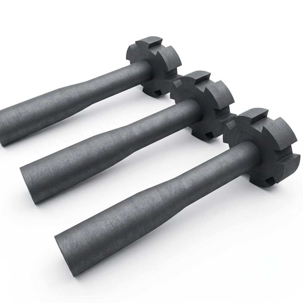
Anti-oxidation treated graphite rotors and shafts for molten aluminum degassing. Designed for long life and efficient hydrogen removal in foundries.

Target Buyer:Foundry procurement and metallurgical engineers.
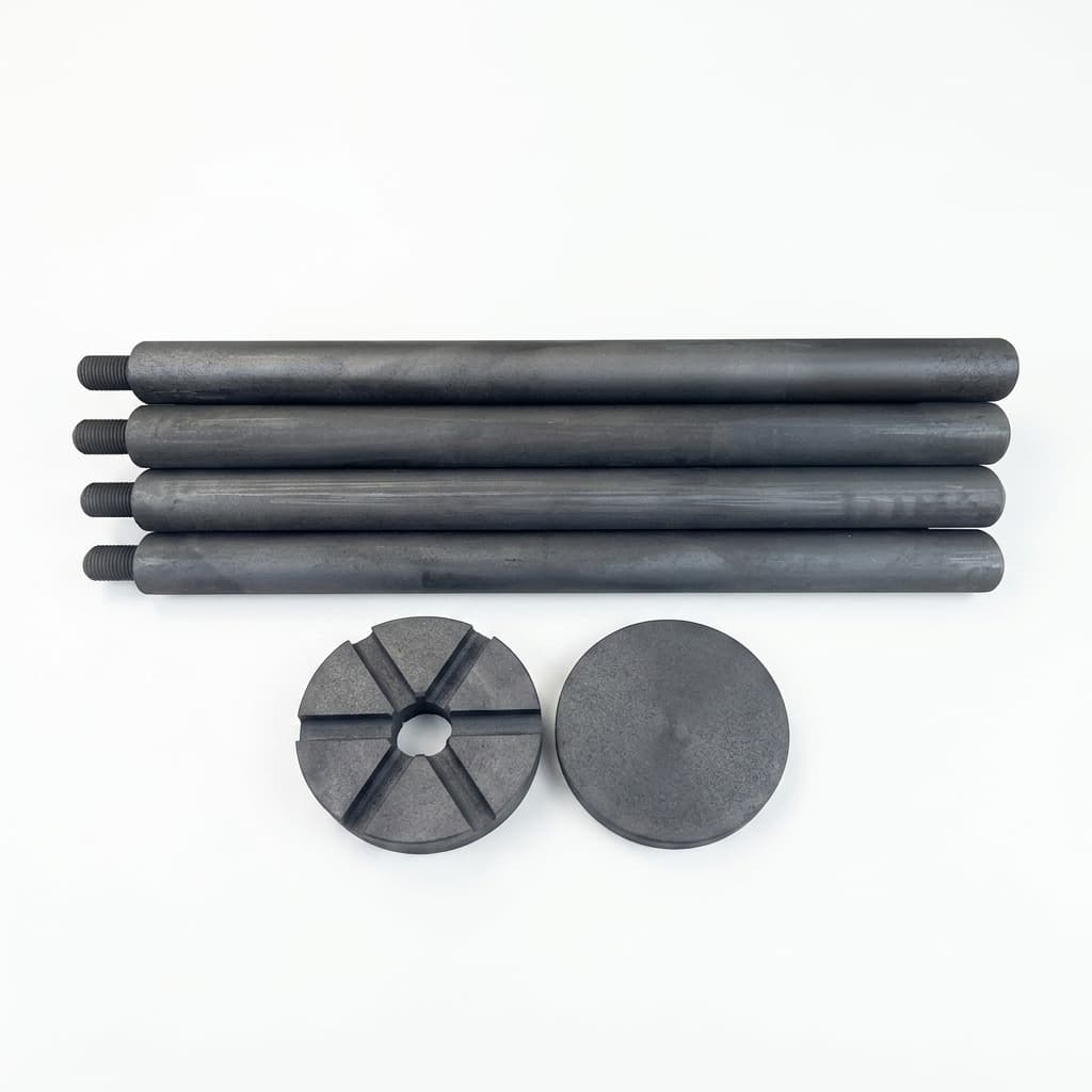
Graphite rotor and shaft for aluminum degassing 1

Capability Highlights

  • Advanced anti-oxidation treatment
  • High thermal shock resistance
  • Optimized impeller design for bubble dispersion

Typical Applications

  • Aluminum Foundries
  • Molten Metal Degassing

Engineering Focus

  • Oxidation resistance coating
  • Rotor thread strength
  • Impeller geometry

Key Evaluation Matrix

MetricTypical RangeWhy It Matters
Service Life30 - 60 days (varies by usage)Reduces downtime and consumable costs.
Oxidation ResistanceAnti-oxidation treatment by melt temperature and cycleRotor life is usually limited by oxidation and attack near the liquid line.
Thread EngagementMatched shaft and rotor-head thread designThread mismatch causes wobble, breakage, or difficult field replacement.
Bubble DispersionImpeller geometry matched to degassing practiceGas dispersion efficiency affects hydrogen removal and melt quality.
Engineering Datasheet

Product-Level Technical Specifications

Values below are RFQ planning targets, not blanket guarantees. Final acceptance criteria should be frozen against drawings, process conditions, equipment model, and buyer qualification requirements.

ParameterTarget / Typical ScopeEngineering Note
Rotor assembly scopeGraphite shaft, rotor head, impeller, thread, coupling, and optional spare heads by drawingShaft and rotor head should be reviewed as an assembly when thread fit and balance affect service life.
Graphite gradeFine-grain graphite selected by oxidation resistance, thermal shock, and molten aluminum exposureGraphite grade and treatment determine liquid-line wear, neck breakage, and erosion behavior.
Anti-oxidation treatmentImpregnation or coating route defined for molten aluminum temperature, flux, and degassing cycleTreatment depth and exposed graphite surfaces should be reviewed before service-life claims.
Thread and coupling interfaceMetric, imperial, or machine-specific thread with engagement length and torque expectationThread failure or poor matching between shaft and head is a common premature failure point.
Impeller geometryBlade count, outlet holes, head diameter, flow path, and bubble dispersion features by drawingGeometry affects gas dispersion, hydrogen removal efficiency, and mechanical load.
Service conditionMolten aluminum temperature, rotation speed, gas type, flux exposure, and expected service intervalService life varies widely unless the operating window and maintenance practice are stated.

Trace Impurity Review Table

Semiconductor programs should define restricted elements before sample production. The table helps procurement and process teams turn purity expectations into a measurable qualification file.

ElementTypical LimitWhy Controlled
Oxidation lossAnti-oxidation route selected by temperature and exposure timeOxidation near the liquid line is a leading cause of shaft thinning and breakage.
Thermal shock crackingPreheat and operating procedure reviewed with graphite gradeFast immersion and thermal cycling can crack rotors even when material quality is acceptable.
Thread damageVisual and dimensional thread acceptance requiredDamaged or mismatched threads increase wobble, assembly failure, and head loss risk.
Surface erosion / metal wettingReviewed by alloy, flux, chlorine-free process needs, and treatment routeMolten-metal chemistry and flux exposure drive rotor erosion and surface degradation.

RFQ Evidence Package

These records reduce ambiguity before sample approval and repeat-order release.

  1. Rotor assembly drawing with shaft length, diameter, thread, coupling, head geometry, blade count, and gas path.
  2. Service-condition sheet covering melt temperature, alloy, gas type, rotation speed, flux exposure, and target lifetime.
  3. Graphite grade and anti-oxidation treatment route tied to liquid-line wear and thermal shock risk.
  4. Thread and critical-dimension report for shaft/head matching and machine interface.
  5. Packing photos protecting shaft straightness, thread ends, rotor heads, and labeled spare kits.

Equipment Compatibility Review

Compatibility should be treated as an engineering review, not a catalog claim. Equipment-family language helps buyers route the RFQ, while final production still depends on drawings, samples, coating allowance, and acceptance criteria.

Equipment FamilyCompatible Part ScopeBuyer Validation Required
Aluminum rotary degassing unitsGraphite shafts, rotor heads, impellers, threaded assemblies, and replacement consumable kits.Confirm machine model, shaft length, thread, rotor head drawing, rotation speed, gas flow, and bath depth.
Foundry melt treatment linesAnti-oxidation graphite rotors and shafts for ladles, crucible furnaces, and holding furnaces.Confirm alloy family, melt temperature, flux exposure, preheat practice, target service life, and failure location.
Custom OEM degassing assembliesDrawing-based graphite rotor assemblies with custom coupling, head, or impeller geometry.Confirm 2D/3D drawing, mating drive interface, assembly balance needs, packing method, and spare strategy.
Open full OEM compatibility matrix

Product Selection Logic

Decision FactorSelection LogicBuyer Check
Melt-line attackSelect anti-oxidation treatment and shaft design around the most exposed liquid-line region.Provide melt temperature, treatment cycle, and current breakage location.
Degassing efficiencyRotor-head geometry must match gas flow and bubble dispersion requirements.Send rotor drawing, shaft length, rotation speed, and gas flow assumptions.
Thread compatibilityMatched shaft and rotor-head threads reduce wobble and field replacement issues.Specify thread standard and whether assembled or separate supply is preferred.

Manufacturing and QC Flow

StageProduction / QC CheckpointBuyer Evidence
1. Degassing process reviewConfirm melt temperature, rotor speed, gas flow, shaft length, and service-life target.Rotor drawing, current lifetime, and failure photos.
2. Graphite and treatment routeSelect graphite grade, anti-oxidation treatment, and shaft or head configuration.Material and treatment proposal tied to molten-aluminum exposure.
3. Machining and assemblyMachine shaft, rotor head, thread, and impeller geometry for stable operation.Dimensional and thread-fit inspection.
4. Surface and balance checkReview coating or impregnation surface, straightness, and assembled fit.Visual check and assembly photos.
5. Export packingProtect long shafts and rotor heads from bending, thread impact, and moisture.Separated or assembled packing plan.

RFQ Checklist

  1. Shaft length and diameter
  2. Rotor head design (provide drawing)
  3. Expected lifespan target

Risk Controls

  • Neck snapping at the liquid line: Reinforced shaft design and deep anti-oxidation impregnation.

Product Gallery

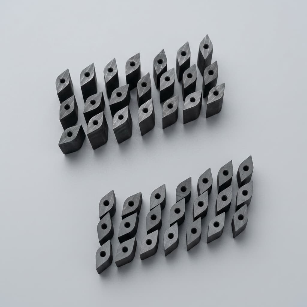
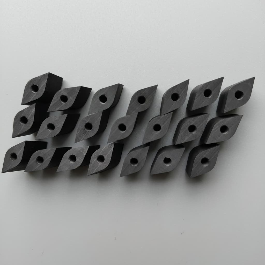
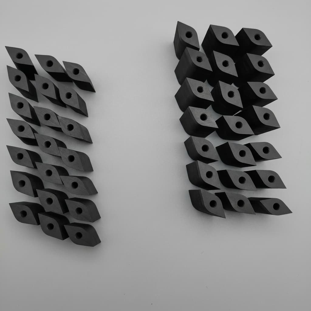
Graphite rotor and shaft for aluminum degassing 2
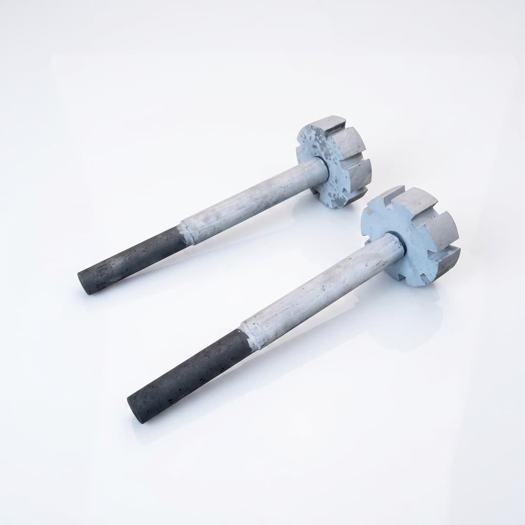
Graphite rotor and shaft for aluminum degassing 3
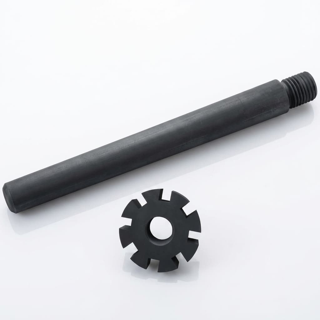
Graphite rotor and shaft for aluminum degassing 4
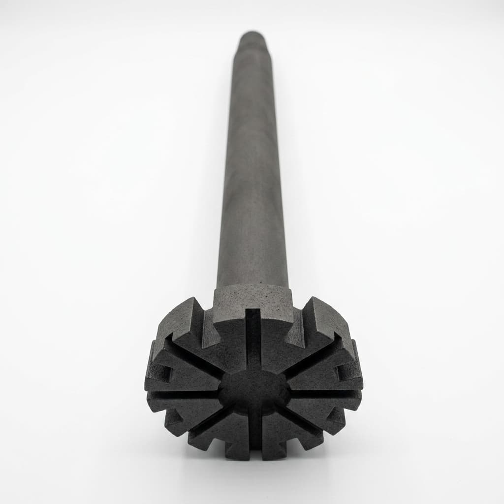
Graphite rotor and shaft for aluminum degassing 5
Anti-oxidation graphite rotor for molten aluminum degassing 1
Anti-oxidation graphite rotor for molten aluminum degassing 2
Anti-oxidation graphite rotor for molten aluminum degassing 3
Anti-oxidation graphite rotor for molten aluminum degassing 4

Buyer FAQ

Do you supply the shaft and rotor head together?

Yes, we supply them assembled or separately, with precision-matched threads.

What usually limits graphite rotor life in aluminum degassing?

Oxidation and attack near the liquid line are common limits, followed by thread mismatch, shaft bending, or rotor-head breakage.

Should the shaft and rotor head be ordered together?

Ordering together improves thread matching and balance, but separate supply is possible when the interface standard is clear.

What data improves rotor quotation accuracy?

Send shaft length, rotor-head drawing, melt temperature, rotation speed, gas flow, current lifetime, and failure photos.

Related Resources

  • OEM: Custom Parts
  • OEM Compatibility Matrix
  • Quality & Metrology
  • Contact / RFQ
  • Solution: Industrial Graphite Replacement

Procurement Next Steps

  • Compare the full product portfolio before locking material architecture.
  • Match the part to a process solution for thermal-field and contamination constraints.
  • Review OEM capability controls for machining, coating, purification, and export packaging.
  • Send a drawing-based RFQ with process, material grade, tolerances, quantity, and delivery target.

Inquiry Email

[email protected]

Email app

Include process, product type, drawing status, purity/coating target, dimensions, quantity forecast, operating conditions, and delivery date.

Instant Chat

+8618857971991

Chat on WhatsApp

Best for quick drawing checks, process fit questions, and RFQ clarification.