SiC GraphiteSiC Graphite
Start inquiry
SiC GraphiteSiC Graphite
WhatsApp
SiC GraphiteSiC Graphite

China-based industrial OEM supplier supporting customization, quality control, and global delivery.

Inquiry Email

[email protected]

Email app

Include process, product type, drawing status, purity/coating target, dimensions, quantity forecast, operating conditions, and delivery date.

Instant Chat

+8618857971991

Chat on WhatsApp

Best for quick drawing checks, process fit questions, and RFQ clarification.

Products
  • SiC Crystal Growth Crucible
  • High-Purity Graphite Heater
  • Graphite Hot Zone
  • Rigid Carbon Felt Insulation
  • CVD SiC Coated Susceptor
  • SiC Coated Wafer Carrier
  • SiC Coated Dummy Wafer
  • C/C Composite Fasteners
  • C/C Composite Trays
  • Vacuum Pump Graphite Vanes
  • Aluminum Degassing Graphite Rotor
  • TaC Coated Graphite Crucible
  • Tantalum Carbide Guide Ring
  • TaC Coated Susceptor
Solutions
  • SiC PVT Crystal Growth
  • MOCVD & Epitaxy
  • Semiconductor Thermal Field
  • Vacuum Furnace Hot Zone
  • High-Temperature Carbon Composites
  • Industrial Graphite Replacement
OEM Capabilities
  • High-Purity Graphite Machining
  • CVD SiC Coating
  • C/C Composite Fabrication
  • Purity and Ash Control
  • Drawing-Based Custom Parts
  • Inspection and Export Packaging
Resources
  • Blog
  • About
  • Contact / RFQ
  • Quality & Metrology
  • OEM Compatibility Matrix
  • Privacy Policy
  • Terms of Service
  • Cookie Policy
© 2026 SiC Graphite. All Rights Reserved.|Supply chain combines Liaoyang Xingde graphite thermal-field manufacturing with Qingdao Chijiu CVD SiC coating and C/C composite capabilities.
← Back to Products

CVD SiC Coated Susceptor

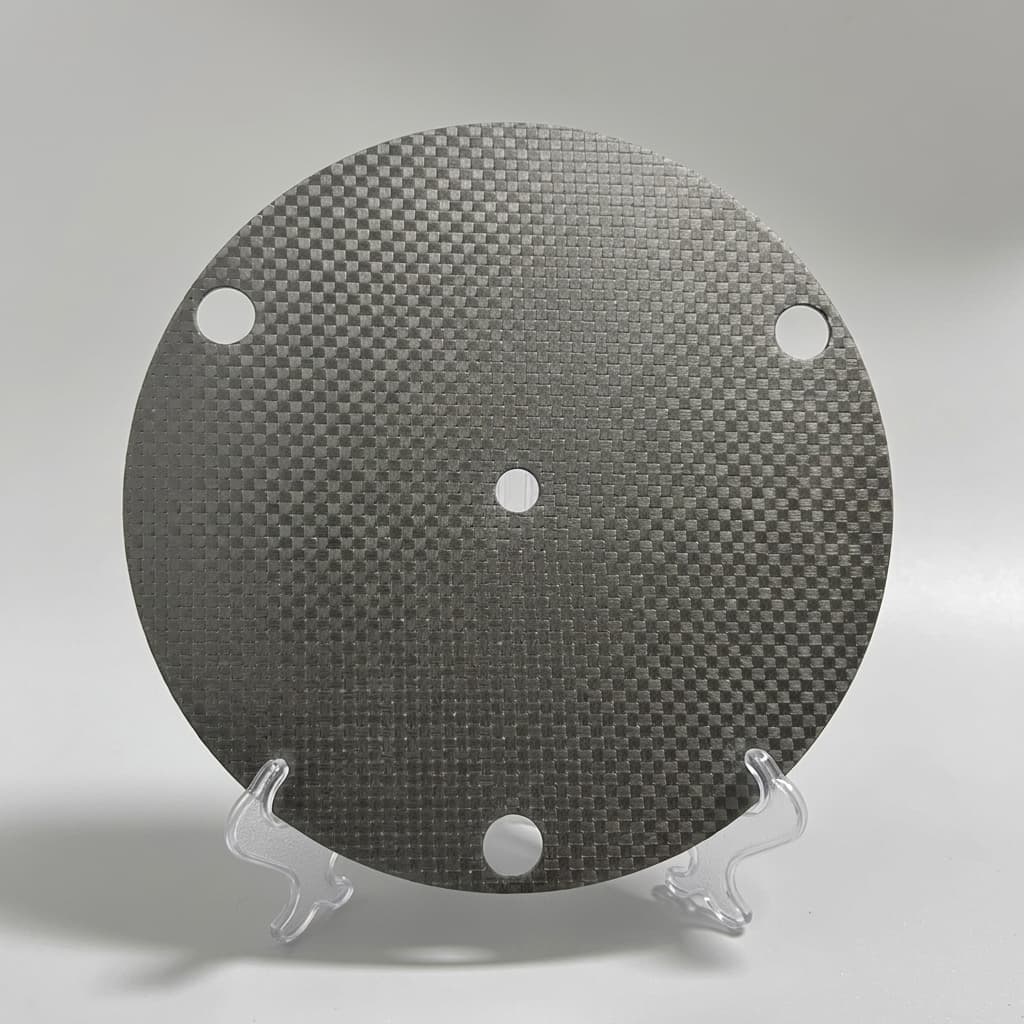
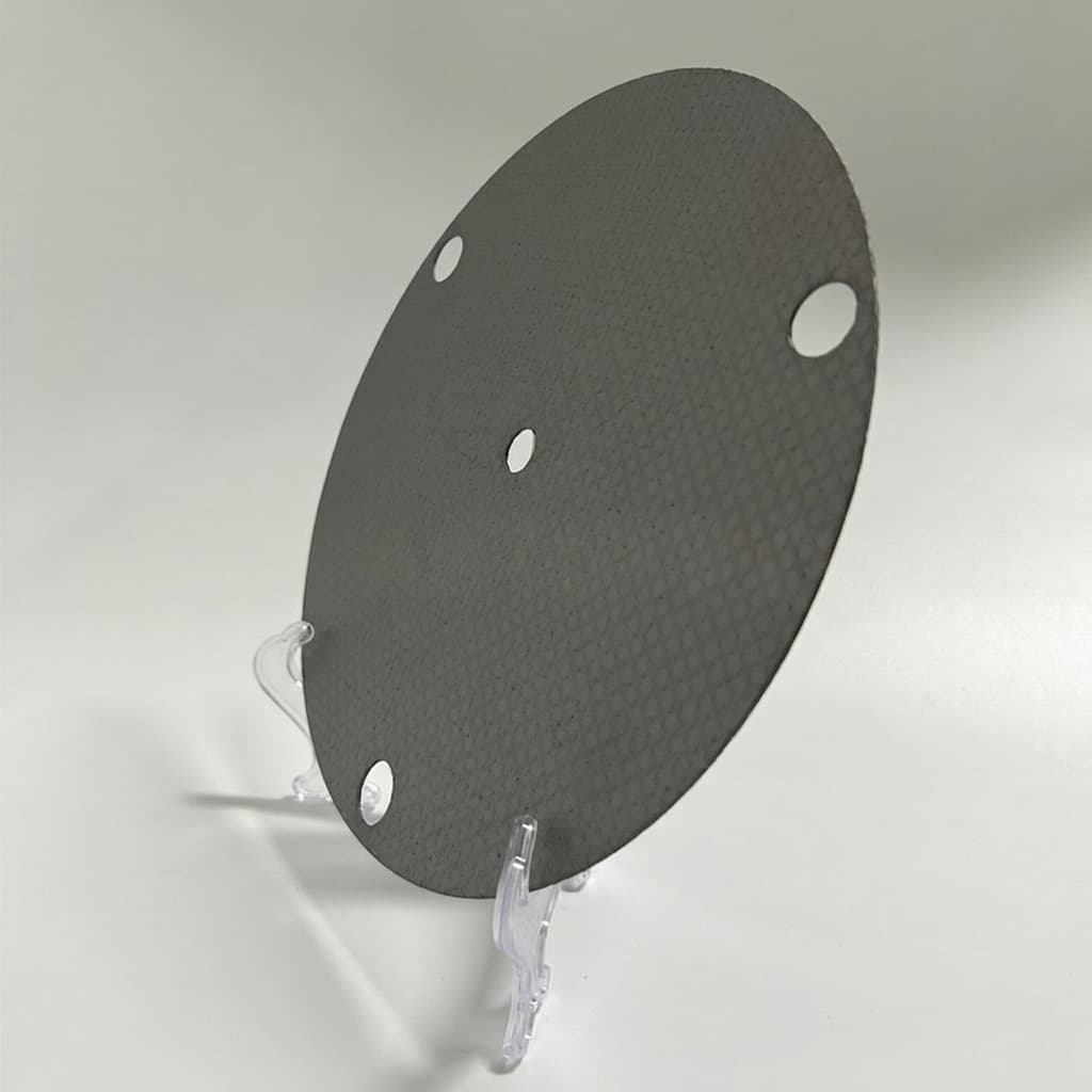
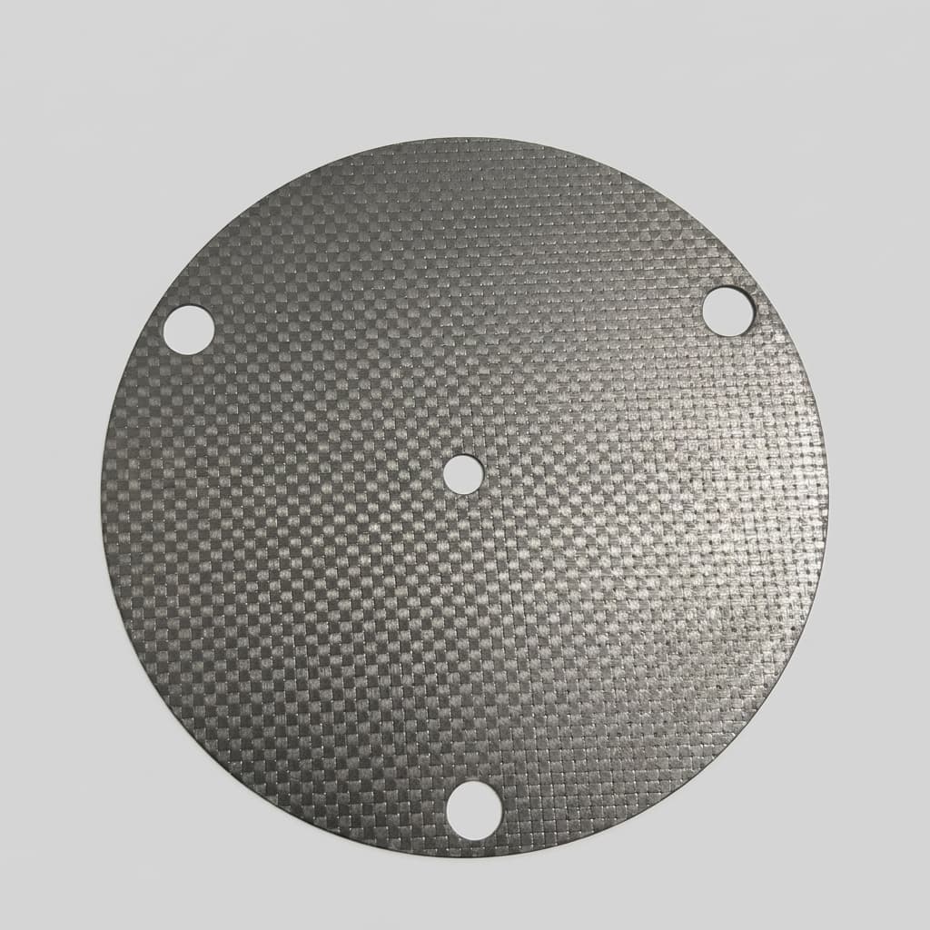
Precision graphite susceptors with high-purity CVD SiC coating for MOCVD and silicon epitaxy. The coating helps improve resistance to corrosive gases and reduce carbon particle contamination risk.

Target Buyer:Process engineers in semiconductor fabs.
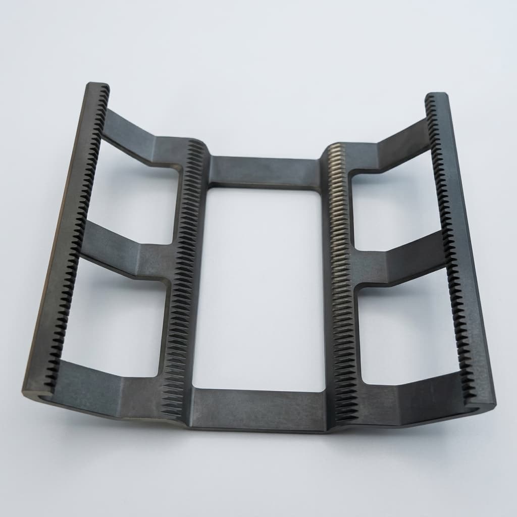
CVD SiC coated graphite susceptor for MOCVD epitaxy 1

Capability Highlights

  • Dense CVD SiC coating targets
  • Ultra-high purity
  • Thermal and chemical resistance for epitaxy environments

Typical Applications

  • MOCVD / Epitaxy
  • RTP (Rapid Thermal Processing)
  • LED / Power Device Manufacturing

Engineering Focus

  • Coating thickness uniformity
  • Surface roughness (Ra)
  • CTE matching between graphite and SiC

Key Evaluation Matrix

MetricTypical RangeWhy It Matters
Coating Thickness80 - 120 µmEnsures longevity against etching gases.
Coating UniformityThickness map or coupon check by projectThin edges or pockets become the first failure point in corrosive epitaxy gases.
Base Graphite MatchCTE and density matched to CVD SiC coatingPoor substrate matching drives coating cracks, peeling, and exposed graphite.
Surface FinishRa target specified for wafer pocket or sealing surfaceSurface finish affects wafer slip, particle risk, and thermal uniformity.
Engineering Datasheet

Product-Level Technical Specifications

Values below are RFQ planning targets, not blanket guarantees. Final acceptance criteria should be frozen against drawings, process conditions, equipment model, and buyer qualification requirements.

ParameterTarget / Typical ScopeEngineering Note
Base materialHigh-purity isostatic graphite, grade selected by CTE and densitySubstrate match reduces coating stress and exposed-graphite failure risk.
Coating typeHigh-purity CVD beta-SiC coatingDense CVD SiC protects graphite from H2 / HCl / NH3 process exposure and particle release.
Coating thicknessTypical 80-120 um; project range can be reviewedThickness target depends on gas-facing surfaces, pocket geometry, and lifetime target.
Surface roughnessRa target defined by wafer-contact or gas-facing surfacePocket, sealing, and handling surfaces should not share one generic finish requirement.
Thermal expansion reviewBase graphite CTE matched to coating route and operating cycleThermal mismatch is a common driver of cracks, edge lift, and premature coating failure.
Dimensional toleranceDrawing-defined CTQ features; post-coating allowance requiredFinal fit should be checked after coating on pockets, OD/ID, grooves, and mounting faces.

Trace Impurity Review Table

Semiconductor programs should define restricted elements before sample production. The table helps procurement and process teams turn purity expectations into a measurable qualification file.

ElementTypical LimitWhy Controlled
Na / KBuyer-defined ppm or ppb targetAlkali metals can contaminate high-value epitaxy and wafer-contact processes.
Al / FeBuyer-defined trace-metal limitsCommon metallic contaminants that should be bounded before qualification samples.
Cr / NiRestricted where corrosion or alloy contamination mattersTransition metals can affect sensitive semiconductor process acceptance.
V / TiProject-specific limits for SiC and power-device programsOften reviewed when substrate purity and coating purity are part of buyer qualification.

RFQ Evidence Package

These records reduce ambiguity before sample approval and repeat-order release.

  1. Marked coating map showing coated, uncoated, masked, wafer-contact, and sealing surfaces.
  2. First-article dimensional record for CTQ features after machining and coating.
  3. Visual coating inspection photos and agreed thickness-verification method or coupon check.
  4. Lot COA or project-defined trace-element table for substrate and coating qualification.
  5. Clean handling and export packing photos before shipment release.

Equipment Compatibility Review

Compatibility should be treated as an engineering review, not a catalog claim. Equipment-family language helps buyers route the RFQ, while final production still depends on drawings, samples, coating allowance, and acceptance criteria.

Equipment FamilyCompatible Part ScopeBuyer Validation Required
Silicon epitaxy reactorsSingle-wafer, barrel, and pancake-style SiC coated graphite susceptors.Confirm wafer size, gas-facing surfaces, AMAT / ASM / LPE-style interface, and drawing revision.
MOCVD and compound semiconductor reactorsCustom susceptors, trays, rings, plates, and gas-facing coated graphite components.Confirm Aixtron / Veeco-style carrier geometry, pocket layout, rotation interface, and coating map.
RTP and annealing toolsThermal-processing carriers and graphite fixtures where SiC coating is required.Confirm ramp rate, thermal shock exposure, flatness requirement, and handling contact areas.
Open full OEM compatibility matrix

Product Selection Logic

Decision FactorSelection LogicBuyer Check
Corrosive process gasChoose CVD SiC coated graphite for MOCVD, epitaxy, HCl, NH3, or particle-sensitive wafer handling.Specify gas environment, wafer size, equipment model, and lifetime target.
Coating feasibilityDeep pockets, blind holes, sharp edges, and hidden surfaces may need DFM changes before coating.Ask for coating-thickness targets and note surfaces that must remain uncoated.
Substrate matchBase graphite must be chosen for CTE, density, and surface quality, not only machining cost.Confirm CTE matching logic and first-article visual/coating inspection scope.

Manufacturing and QC Flow

StageProduction / QC CheckpointBuyer Evidence
1. Coating DFMReview pockets, blind areas, edges, masked surfaces, and coating-thickness target.Marked drawing with coated, uncoated, and critical wafer-contact surfaces.
2. Substrate machiningMachine graphite substrate with CTE, density, and surface preparation matched to CVD SiC.Base material selection note and pre-coating inspection record.
3. CVD SiC coatingDeposit dense SiC coating with attention to pockets, edges, and thermal-stress risk.Coating thickness target and inspection method agreed before production.
4. Final inspectionCheck visible defects, coating continuity, dimensions, and wafer-contact surfaces.Inspection report, photos, or coupon result depending on order scope.
5. Clean export packingProtect polished or coated surfaces from abrasion, fingerprints, and impact.Individual wrapping, separators, and packing photos.

RFQ Checklist

  1. Provide 2D/3D drawings
  2. Specify target coating thickness (e.g., 80-120µm)
  3. Identify equipment model (e.g., LPE, Aixtron, Veeco)

Risk Controls

  • Coating micro-cracks: Strict CTE matching of base graphite and precise CVD temp profiling.

Product Gallery

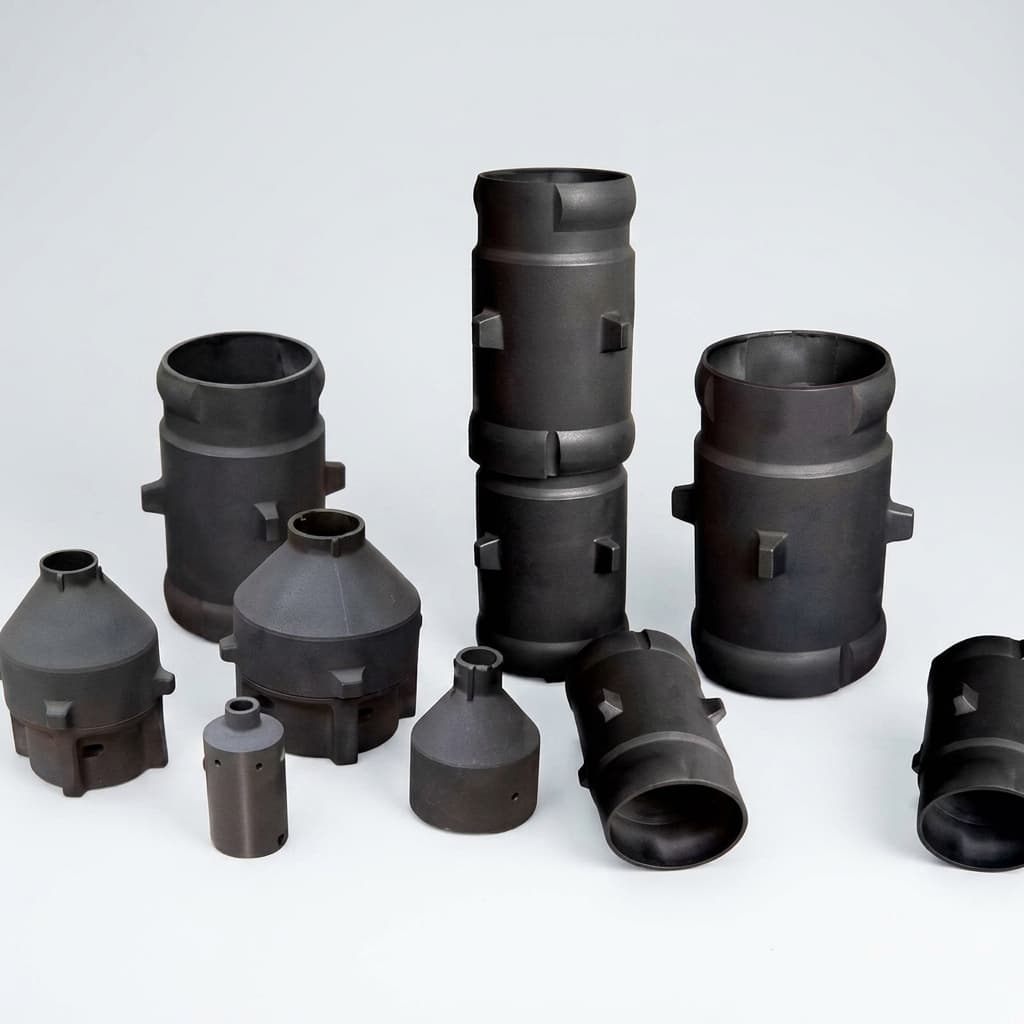
CVD SiC coated graphite susceptor for MOCVD epitaxy 2
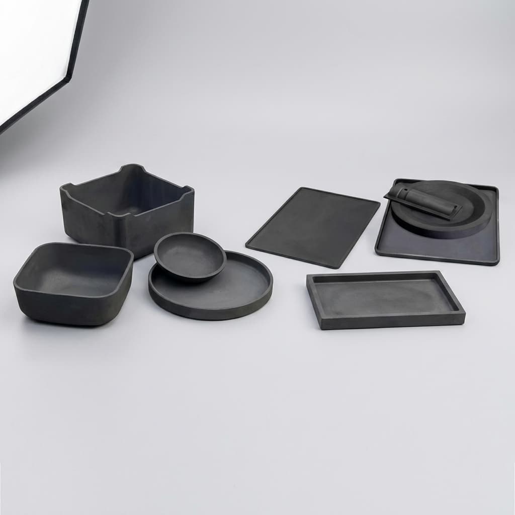
CVD SiC coated graphite susceptor for MOCVD epitaxy 3
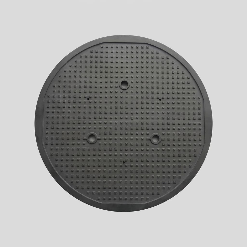
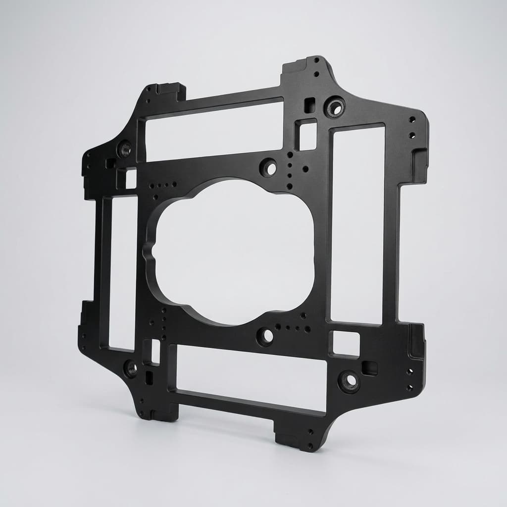
CVD SiC coated graphite susceptor for MOCVD epitaxy 4
CVD SiC coated graphite susceptor for MOCVD epitaxy 5
SiC coated MOCVD susceptor for wafer processing 1
SiC coated MOCVD susceptor for wafer processing 2
SiC coated MOCVD susceptor for wafer processing 3

Buyer FAQ

What is the typical lifetime of your susceptors?

It depends on the process recipe, but dense coating and controlled base graphite selection can support longer intervals before recoating or replacement.

What is the most common cause of SiC coating failure?

Early failure usually comes from substrate mismatch, coating shadow areas, sharp edges, or thermal cycling that creates cracks and exposes the graphite base.

Do all surfaces need the same SiC coating thickness?

No. Wafer-contact areas, gas-facing surfaces, edges, and masked interfaces should be marked on the drawing before the CVD coating route is finalized.

What evidence should a buyer request for coated parts?

Ask for agreed coating-thickness checks, visual defect inspection, critical dimensional checks after coating, and clean packing photos for sensitive surfaces.

Related Resources

  • OEM: CVD SiC Coating
  • OEM Compatibility Matrix
  • Quality & Metrology
  • Contact / RFQ
  • Solution: MOCVD and Epitaxy
  • Guide: CVD SiC vs Bare Graphite

Procurement Next Steps

  • Compare the full product portfolio before locking material architecture.
  • Match the part to a process solution for thermal-field and contamination constraints.
  • Review OEM capability controls for machining, coating, purification, and export packaging.
  • Send a drawing-based RFQ with process, material grade, tolerances, quantity, and delivery target.

Inquiry Email

[email protected]

Email app

Include process, product type, drawing status, purity/coating target, dimensions, quantity forecast, operating conditions, and delivery date.

Instant Chat

+8618857971991

Chat on WhatsApp

Best for quick drawing checks, process fit questions, and RFQ clarification.