SiC GraphiteSiC Graphite
Start inquiry
SiC GraphiteSiC Graphite
WhatsApp
SiC GraphiteSiC Graphite

China-based industrial OEM supplier supporting customization, quality control, and global delivery.

Inquiry Email

[email protected]

Email app

Include process, product type, drawing status, purity/coating target, dimensions, quantity forecast, operating conditions, and delivery date.

Instant Chat

+8618857971991

Chat on WhatsApp

Best for quick drawing checks, process fit questions, and RFQ clarification.

Products
  • SiC Crystal Growth Crucible
  • High-Purity Graphite Heater
  • Graphite Hot Zone
  • Rigid Carbon Felt Insulation
  • CVD SiC Coated Susceptor
  • SiC Coated Wafer Carrier
  • SiC Coated Dummy Wafer
  • C/C Composite Fasteners
  • C/C Composite Trays
  • Vacuum Pump Graphite Vanes
  • Aluminum Degassing Graphite Rotor
  • TaC Coated Graphite Crucible
  • Tantalum Carbide Guide Ring
  • TaC Coated Susceptor
Solutions
  • SiC PVT Crystal Growth
  • MOCVD & Epitaxy
  • Semiconductor Thermal Field
  • Vacuum Furnace Hot Zone
  • High-Temperature Carbon Composites
  • Industrial Graphite Replacement
OEM Capabilities
  • High-Purity Graphite Machining
  • CVD SiC Coating
  • C/C Composite Fabrication
  • Purity and Ash Control
  • Drawing-Based Custom Parts
  • Inspection and Export Packaging
Resources
  • Blog
  • About
  • Contact / RFQ
  • Quality & Metrology
  • OEM Compatibility Matrix
  • Privacy Policy
  • Terms of Service
  • Cookie Policy
© 2026 SiC Graphite. All Rights Reserved.|Supply chain combines Liaoyang Xingde graphite thermal-field manufacturing with Qingdao Chijiu CVD SiC coating and C/C composite capabilities.
← Back to Products

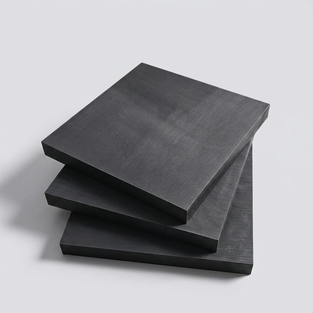
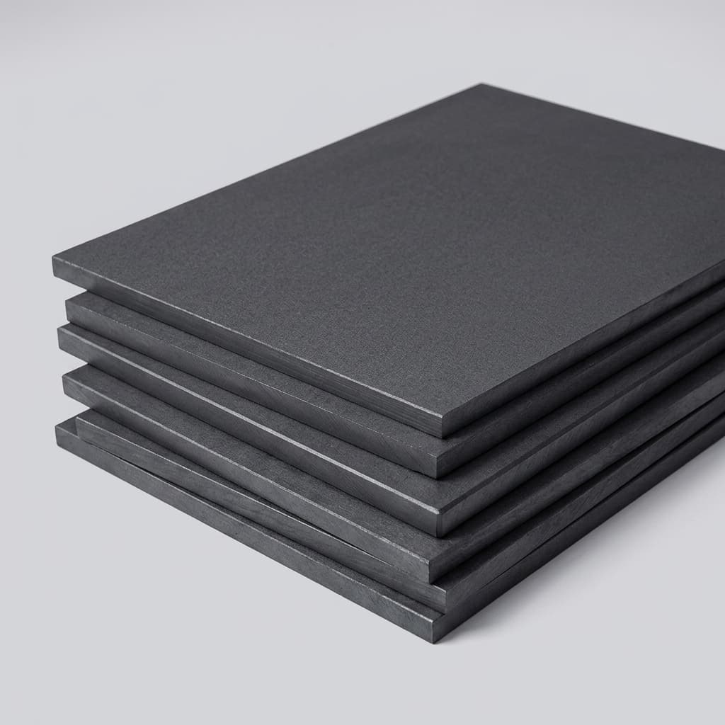
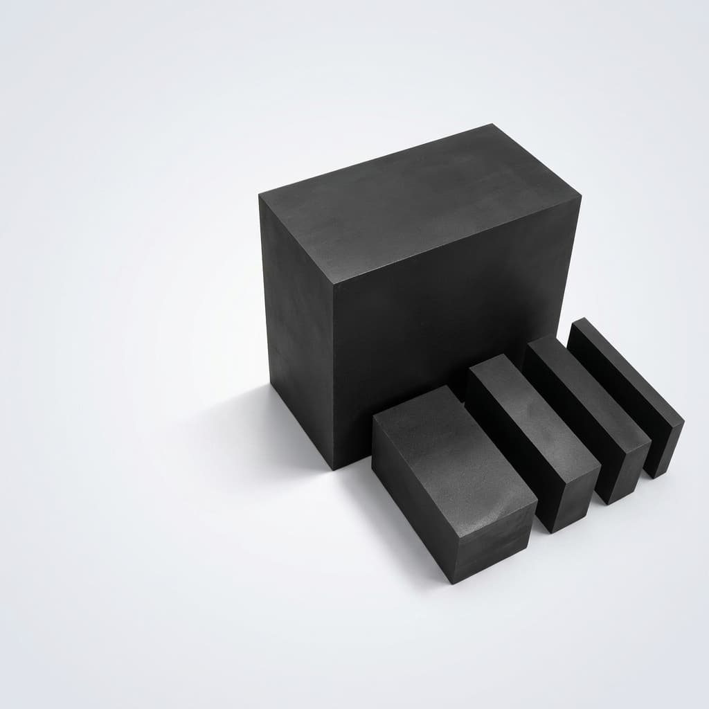
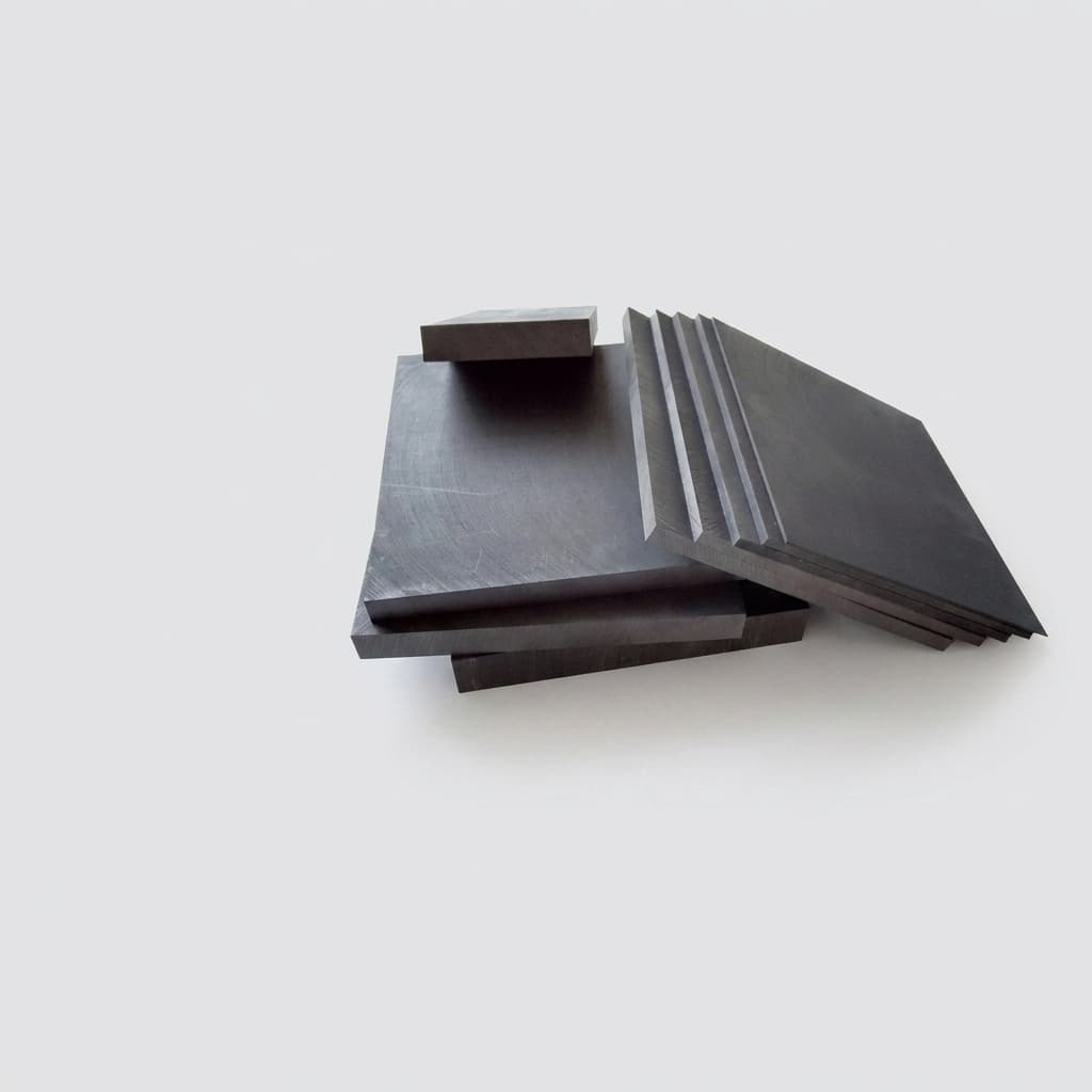
C/C Composite Trays

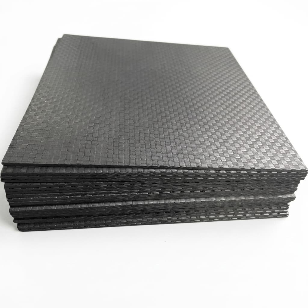
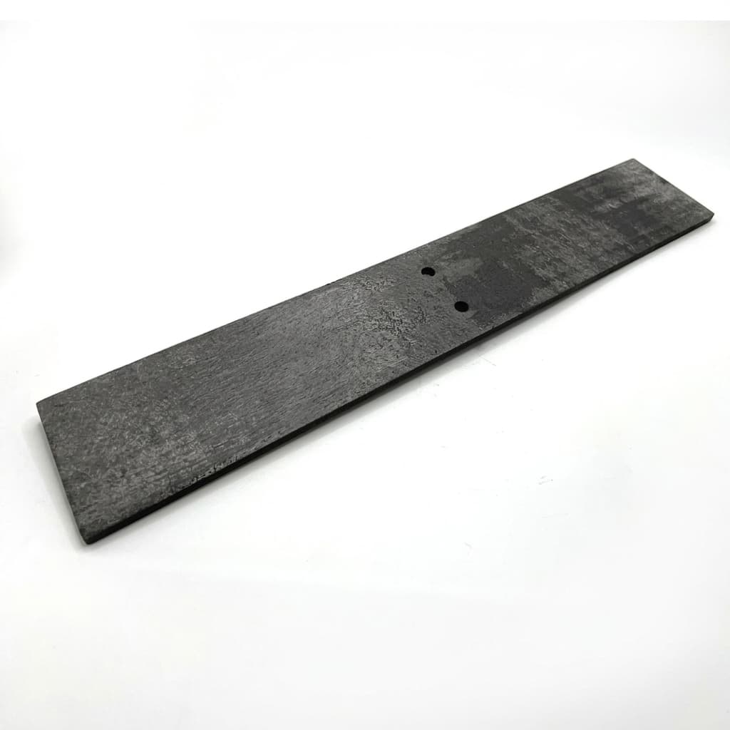
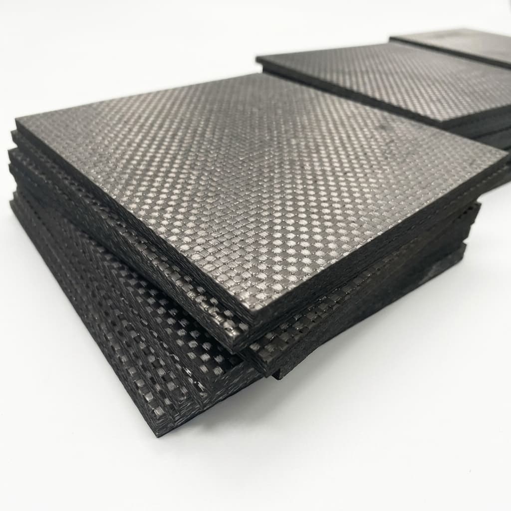
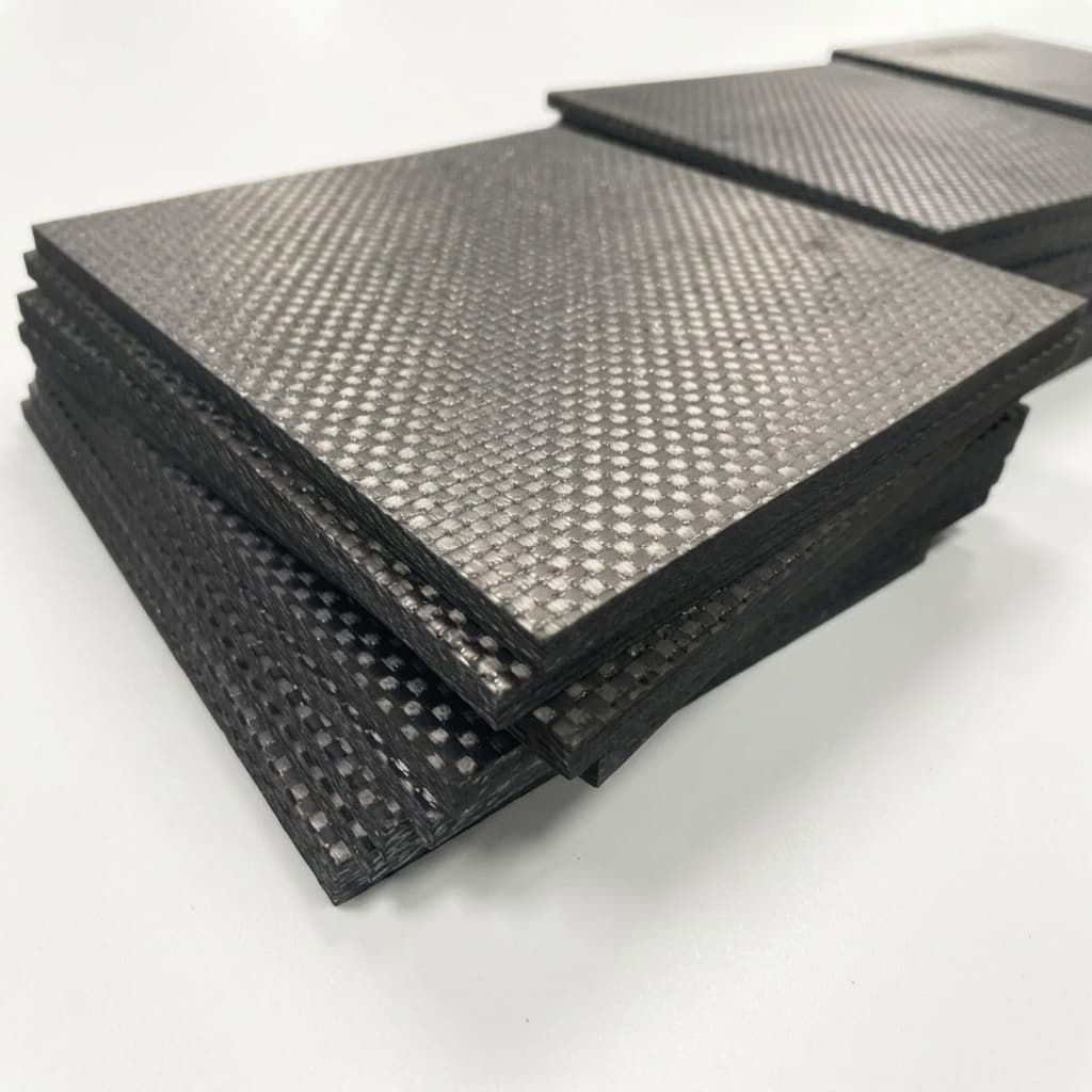
High-strength, lightweight C/C composite trays and fixtures for heat treatment and brazing. Offers significantly longer lifespan and higher load capacity than conventional graphite trays.

Target Buyer:Heat treatment plant managers and process engineers.
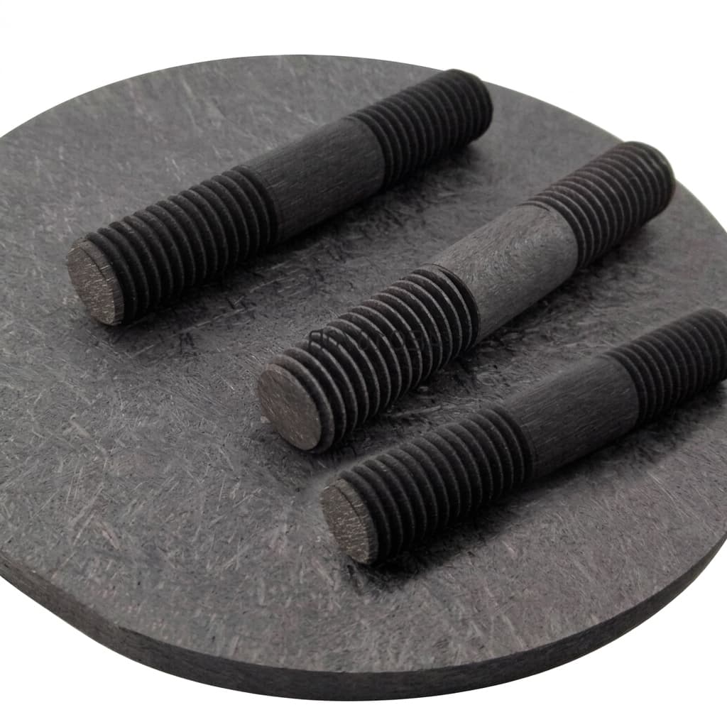
C/C composite tray and plate for vacuum furnace fixtures 1

Capability Highlights

  • Lightweight yet highly load-bearing
  • Excellent thermal shock resistance
  • Minimal warping over time

Typical Applications

  • Vacuum Brazing
  • Sintering
  • Heat Treatment Fixturing

Engineering Focus

  • Load-bearing capacity at temperature
  • Flatness over time
  • Thermal cycling durability

Key Evaluation Matrix

MetricTypical RangeWhy It Matters
Flexural Strength> 120 MPaAllows for thinner, lighter trays holding heavy loads.
Fiber Architecture2D or 3D C/C composite by load directionFiber orientation controls strength, thread retention, and long-term deformation.
Operating AtmosphereVacuum or inert gas; oxidation protection if requiredC/C composite strength is excellent at temperature, but oxygen exposure must be managed.
Load CaseStatic load, fixture spacing, and thermal-cycle countTray sag, bolt shear, and creep risk depend on the real support condition.
Engineering Datasheet

Product-Level Technical Specifications

Values below are RFQ planning targets, not blanket guarantees. Final acceptance criteria should be frozen against drawings, process conditions, equipment model, and buyer qualification requirements.

ParameterTarget / Typical ScopeEngineering Note
Tray architecture2D or 3D C/C composite tray, plate, rail, fixture, or support frameArchitecture should follow load direction, support spacing, fixture contact, and thermal-cycle stress.
Load capacityBuyer-defined static load, distributed load, point load, and support spanA tray capacity claim has no value unless support spacing and operating temperature are defined.
Operating environmentVacuum or inert furnace review by temperature, atmosphere, and cycle countOxidation exposure, cleaning steps, and quench conditions should be stated before material selection.
Flatness and warpageInitial flatness and allowable in-service deformation by applicationHeat treatment trays often fail by sagging or warping before complete fracture.
Machined featuresSlots, holes, rails, pockets, locating pins, and handling notches by drawingMachined features can concentrate stress and should be reviewed with fiber direction.
Weight reduction targetCompared against graphite, molybdenum, or refractory-metal fixture baselineWeight reduction matters for energy use, handling, and thermal mass, but must not compromise fixture stiffness.

Trace Impurity Review Table

Semiconductor programs should define restricted elements before sample production. The table helps procurement and process teams turn purity expectations into a measurable qualification file.

ElementTypical LimitWhy Controlled
Fiber architecture2D / 3D / reinforced route selected by load directionTray strength and sag resistance depend on fiber direction, not only thickness.
Density / porosityProject-defined density and impregnation routeDensity affects stiffness, oxidation behavior, machining edges, and usable service life.
Oxidation boundaryVacuum / inert use; coating or treatment reviewed for oxygen exposureHigh-temperature carbon fixtures need atmosphere control to prevent accelerated material loss.
Surface debris / edge damageVisual acceptance and packing method defined by buyerLarge trays can abrade, chip, or shed debris if packed without separators and edge protection.

RFQ Evidence Package

These records reduce ambiguity before sample approval and repeat-order release.

  1. Tray drawing with length, width, thickness, support span, holes, slots, rails, and handling features.
  2. Load case defining distributed load, point load, maximum temperature, atmosphere, and cycle count.
  3. Fiber architecture, density, and fabrication route selected against sag, creep, and thermal shock risk.
  4. Flatness or critical dimensional record for sample approval and repeat-order release.
  5. Export packing photos showing separators, edge protection, crate support, and orientation labels.

Equipment Compatibility Review

Compatibility should be treated as an engineering review, not a catalog claim. Equipment-family language helps buyers route the RFQ, while final production still depends on drawings, samples, coating allowance, and acceptance criteria.

Equipment FamilyCompatible Part ScopeBuyer Validation Required
Vacuum heat treatment furnacesC/C trays, plates, rails, shelves, and load-bearing support fixtures.Confirm load distribution, support span, fixture stack, maximum temperature, atmosphere, and cycle count.
Brazing, sintering, and annealing furnacesLightweight C/C fixture plates, carrier trays, frames, and replacement graphite tray upgrades.Confirm part weight, point-load zones, thermal shock exposure, flatness requirement, and handling method.
Semiconductor thermal-field maintenanceC/C carrier plates, support trays, and structural fixture components where graphite is too brittle.Confirm cleanliness boundary, ash target if required, packing evidence, and mating carbon hardware.
Open full OEM compatibility matrix

Product Selection Logic

Decision FactorSelection LogicBuyer Check
Load at temperatureChoose C/C composite when graphite is too brittle or molybdenum adds too much thermal mass.Provide load, support spacing, furnace temperature, and cycle count.
Fiber architecture2D C/C can fit plates and trays; 3D architecture is preferred for multi-directional stress and threads.Clarify bending direction, thread engagement, and any fastener preload.
Oxidation boundaryC/C composite is strongest in vacuum or inert environments; oxygen exposure needs protection.Share atmosphere, leak risk, cleaning practice, and cooldown handling.

Manufacturing and QC Flow

StageProduction / QC CheckpointBuyer Evidence
1. Load-case reviewDefine temperature, support spacing, fastener preload, tray load, and cycle count.Application sketch, fixture drawing, load estimate, and atmosphere notes.
2. Fiber architectureChoose 2D or 3D C/C blank according to bending, shear, and thread loads.Material route with density and architecture recommendation.
3. Densification and machiningProcess C/C blank, then machine threads, holes, plates, and tray geometry.Dimensional report for load-bearing and assembly-critical features.
4. Strength-risk checkReview delamination, thread stripping, sag, and edge damage before shipping.Visual inspection plus agreed mechanical evidence if required.
5. Handling and packingPrevent abrasion and impact on lightweight C/C fixtures during export.Packing photos and handling notes for furnace maintenance teams.

RFQ Checklist

  1. Dimensions (L x W x H)
  2. Maximum load per tray
  3. Operating temperature and atmosphere

Risk Controls

  • Tray warping: Optimized fiber architecture (2D/3D) based on stress models.

Product Gallery

C/C composite tray and plate for vacuum furnace fixtures 2
C/C composite tray and plate for vacuum furnace fixtures 3
C/C composite tray and plate for vacuum furnace fixtures 4
C/C composite tray and plate for vacuum furnace fixtures 5
Machined carbon plate fixture for high-temperature processing 1
Machined carbon plate fixture for high-temperature processing 2
Machined carbon plate fixture for high-temperature processing 3
Machined carbon plate fixture for high-temperature processing 4

Buyer FAQ

How much weight can a C/C tray save vs graphite?

C/C trays are typically 50-70% lighter for the same load capacity, saving significant heating energy.

When is C/C composite a better choice than graphite?

Choose C/C composite when the part carries load, sees repeated thermal shock, needs threaded strength, or fails because graphite is too brittle.

What information is needed for C/C tray or fastener design?

Provide load, support spacing, maximum temperature, atmosphere, cycle count, thread standard, and the current failure mode if replacing another material.

Can C/C composite be used in oxidizing atmospheres?

C/C composite performs best in vacuum or inert gas. If oxygen exposure is expected, the application needs oxidation-risk review and possible protective treatment.

Related Resources

  • Solutions: High-Temp Carbon
  • OEM Compatibility Matrix
  • Quality & Metrology
  • Contact / RFQ
  • OEM: C/C Composite Fabrication
  • Product: C/C Composite Fasteners
  • Guide: C/C Composite vs Molybdenum

Procurement Next Steps

  • Compare the full product portfolio before locking material architecture.
  • Match the part to a process solution for thermal-field and contamination constraints.
  • Review OEM capability controls for machining, coating, purification, and export packaging.
  • Send a drawing-based RFQ with process, material grade, tolerances, quantity, and delivery target.

Inquiry Email

[email protected]

Email app

Include process, product type, drawing status, purity/coating target, dimensions, quantity forecast, operating conditions, and delivery date.

Instant Chat

+8618857971991

Chat on WhatsApp

Best for quick drawing checks, process fit questions, and RFQ clarification.