
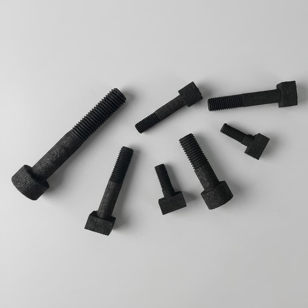
Evaluating SiC Coated Graphite Quality: How to Prevent Coating Delamination
A comprehensive engineering and procurement guide to identifying, preventing, and sourcing CVD SiC-coated graphite susceptors immune to delamination and pinholes.
When specifying graphite consumables for modern semiconductor manufacturing—particularly in Metal-Organic Chemical Vapor Deposition (MOCVD) and Silicon Carbide (SiC) epitaxy—the integrity of the Chemical Vapor Deposition (CVD) SiC coating is the single most critical factor determining production yield and consumable lifespan.
For buyers, procurement teams, and process engineers, the most frustrating and expensive failure mode is coating delamination (peeling or flaking of the SiC layer) and the presence of pinholes. These defects expose the underlying porous graphite to reactive gases, causing uncontrolled outgassing, particle generation, and catastrophic wafer contamination.
As the industry aggressively scales to 8-inch SiC wafers and high-power Gallium Nitride (GaN) devices in 2026, the thermal and mechanical stresses placed on susceptors have reached unprecedented levels. This comprehensive guide explores the structural mechanics behind coating failures, how to prevent them through proper specification, and how to evaluate your graphite supplier's capabilities.
Executive Summary
- The Core Issue: Delamination primarily stems from Coefficient of Thermal Expansion (CTE) mismatch between the graphite substrate and the SiC coating during rapid thermal cycling above 1100 C.
- Pinholes vs. Flaking: Pinholes are often deposition anomalies (flow or temperature issues), while large-scale flaking is a thermomechanical or chemical failure.
- Procurement Strategy: Do not solely negotiate on price. Evaluate the supplier's substrate purification process, CTE matching data, and CVD temperature profiles to calculate the true Total Cost of Ownership (TCO).
Scope and date: This guide was prepared for global engineering and procurement reviews on July 18, 2026. It applies to CVD SiC-coated graphite wafer carriers, susceptors, trays, and gas-facing graphite hardware used in MOCVD, SiC epitaxy, and high-temperature semiconductor processes. It is not a substitute for chamber-specific qualification, destructive coupon testing, or OEM process limits; use it as an RFQ and incoming-inspection framework before running your own thermal-cycle validation.
1. The Anatomy of a Perfect SiC Coating
To understand why a coating fails, we must first define what a "perfect" coating looks like. In semiconductor applications, bare isostatic graphite is insufficient because it is porous (typically 10-15% porosity), allowing it to trap atmospheric gases, moisture, and chemical residues. When heated in a vacuum or controlled atmosphere, these trapped impurities outgas, poisoning the sensitive epitaxial layer.
To seal the graphite, a high-purity layer of Silicon Carbide is applied via Chemical Vapor Deposition (CVD). A premium SiC coating exhibits the following characteristics:
- High Density and Zero Porosity: It must be a fully dense, polycrystalline layer that acts as an absolute barrier against gas permeation.
- Optimal Thickness: Typically between 80µm and 120µm. Too thin, and it may not fully seal the surface or withstand chemical etching. Too thick, and internal residual stresses will cause spontaneous cracking.
- High Purity: The coating itself must be above 99.999% (5N) pure, free from metallic contaminants like Iron (Fe), Copper (Cu), or Aluminum (Al).
- Stoichiometric Balance: A precise 1:1 ratio of Silicon to Carbon ensures maximum thermal conductivity and chemical resistance.
- Strong Interfacial Adhesion: The transition from the porous graphite matrix to the dense SiC layer must be mechanically interlocked without excessive residual stress.
When any of these parameters are compromised during manufacturing, the clock starts ticking toward a delamination event.
2. Root Causes of SiC Coating Delamination
Delamination is rarely a random occurrence. It is the physical manifestation of accumulated stress exceeding the adhesive strength of the interface. Let's break down the primary catalysts for this failure.
Cause 1: Coefficient of Thermal Expansion (CTE) Mismatch
The most fundamental cause of interfacial stress is the difference in the Coefficient of Thermal Expansion (CTE) between the graphite substrate and the SiC coating.
During an MOCVD or epitaxial process, the susceptor cycles from room temperature to operating temperatures exceeding 1600 C (and sometimes above 2000 C for SiC epitaxy).
- If the graphite expands significantly more than the SiC coating, the coating is placed under severe tensile stress.
- If the coating expands more than the graphite, it experiences compressive stress, leading to buckling and blistering.
While SiC and isostatic graphite are often paired because their CTEs are relatively close (around 4.0-5.0 x 10^-6/K depending on the grade and temperature), even minor mismatches (e.g., a difference of just plus/minus 0.2 x 10^-6/K) can induce massive shear forces over thousands of thermal cycles.
Figure: Thermomechanical stress at the interface. As temperature rises, CTE mismatch causes the graphite substrate to expand faster than the SiC coating, generating severe shear stress at the edges, eventually leading to delamination.
Cause 2: Improper Deposition Temperature and Morphology
The CVD process used to apply the coating must be tightly controlled. If the deposition temperature is too low (e.g., below 1000 C), the resulting SiC coating may develop a loose, fibrous, or porous morphology rather than the desired dense, polycrystalline structure.
These lower-density coatings lack structural integrity. They act like a sponge rather than a shield. When subjected to the harsh chemical environments of an epitaxial reactor, these porous structures degrade rapidly, cracking and flaking off. High-quality CVD SiC must be deposited at optimized high temperatures to ensure a tightly packed, columnar grain structure that resists both mechanical stress and chemical attack.
Cause 3: Mechanical Impact and Handling Damage
Not all delamination is thermomechanical; much of it is mechanical. High-speed MOCVD equipment subjects susceptors to intense centrifugal forces (rotating at hundreds of RPMs). The wafers themselves—especially rigid materials like Sapphire or Silicon Carbide—can physically impact the susceptor pockets during automated loading and unloading.
A minor scratch or micro-chip on the edge of a susceptor pocket acts as a stress concentrator. Even if the coating doesn't peel immediately, this localized breach allows reactive process gases (like Hydrogen or Ammonia) to penetrate. Once inside, these gases etch the underlying graphite, hollowing it out and creating "boreholes." Without structural support, the overlying SiC coating collapses and flakes away, spreading the damage across the susceptor face.
Cause 4: Chemical Corrosion and Etching
During the cleaning cycles of epitaxial reactors, aggressive halogen gases, particularly Chlorine (Cl2) or Hydrogen Chloride (HCl), are used to remove residual deposits. Over time, these gases can preferentially attack the grain boundaries of the SiC coating.
While SiC is highly chemically resistant, prolonged exposure to high-temperature halogens can weaken the coating matrix. If the coating has any pre-existing micro-cracks or varying stoichiometry (carbon-rich or silicon-rich zones), the chemical attack is accelerated, undermining the coating and causing widespread delamination.
3. The Threat of Pinholes: The Silent Yield Killer
While massive delamination is obvious to the naked eye, pinholes are insidious microscopic defects that can silently destroy batch yields.
Pinholes occur during the CVD deposition process. Inefficient exhaust gas removal or uneven gas flow dynamics within the CVD reactor can create stagnant regions. In these regions, impurities or structural defects form, preventing the SiC layer from achieving full density. Sometimes, "whiskers" or nodules grow, which are later polished off, leaving microscopic pathways straight down to the graphite substrate.
When a susceptor with pinholes is placed in a high-temperature vacuum, the porous graphite underneath outgasses metallic impurities and trapped air directly through these microscopic vents, right into the wafer's epitaxial growth zone. The result? Unexplained background doping, severe lattice defects, and plummeting semiconductor yields.
Preventing pinholes requires advanced fluid dynamics control within the supplier's CVD reactors, ensuring laminar flow and uniform deposition rates across the entire susceptor surface.
4. The Impact of Carrier Gases and Metrology
Hydrogasification via Carrier Gases
The choice between Hydrogen (H2) and Argon (Ar) or Nitrogen (N2) as a carrier gas also dramatically affects coating longevity. Hydrogen is a strong reducing agent at high temperatures. While SiC is generally resistant, any micro-defect exposing the graphite will lead to rapid hydrogasification of the carbon substrate (C + 2H2 -> CH4). This methane generation not only destroys the susceptor but also severely contaminates the carbon doping profile of the growing epitaxial layer.
Advanced Metrology for Defect Detection
Before a susceptor ever enters a reactor, procurement teams should ensure the supplier employs non-destructive testing (NDT). Techniques such as scanning acoustic microscopy (SAM) can detect subsurface voids and delamination before they break the surface. White light interferometry provides nanometer-level topological mapping to verify that the coating roughness remains within the required Ra < 2µm spec, which is critical for wafer slip prevention.
5. Comparing Standard vs. Premium SiC Coatings
To help procurement teams and engineers quantify the difference between a cheap, fast-deposition coating and a premium, engineered coating, consider the following benchmark parameters:
| Specification Metric | Standard Market SiC Coating | Premium High-Yield SiC Coating | Impact on Process |
|---|---|---|---|
| Purity Level | below 99.9% (3N) | above 99.999% (5N) | High purity prevents metal ion contamination in epi layers. |
| Graphite Substrate CTE Matching | General catalog grade used | Custom mapped to SiC batch (plus/minus 0.1 x 10^-6/K) | Exact matching exponentially increases lifespan against delamination. |
| Deposition Temperature | Lower temp (faster, cheaper) | High temp (slow, dense growth) | High-temp yields dense, non-porous structure resistant to pinholes. |
| Coating Thickness Tolerance | plus/minus 30 micrometers | plus/minus 10 micrometers (highly uniform) | Uniformity ensures even thermal distribution across the wafer. |
| Post-Process Inspection | Visual only | Ultrasonic / Microscopic scanning | Advanced inspection catches subsurface micro-cracks before shipping. |
| Lifespan (Thermal Cycles) | 30 - 50 cycles | 100+ cycles | Doubles or triples the ROI of the consumable, reducing downtime. |
6. Engineering & Procurement Sourcing Checklist
When evaluating a new graphite machining and coating supplier for your fabrication facility, use this actionable checklist to audit their capabilities. A reliable supplier should be able to answer these questions transparently:
- CTE Matching Data: Can the supplier provide specific thermal expansion curves for both the raw graphite lot and the applied SiC coating? Do they guarantee a specific variance threshold?
- Substrate Purification: Is the graphite purified before coating? High-temperature halogen purification (above 2500 C) is mandatory to remove iron and vanadium from the substrate.
- CVD Reactor Design: Do they use proprietary or advanced CVD reactor designs that ensure uniform gas flow, preventing pinhole formation?
- Coating Morphology: Can they provide SEM (Scanning Electron Microscope) images of their coating cross-sections demonstrating a dense, columnar, polycrystalline structure without voids?
- Cleaning Protocols: Are the finished susceptors packaged in a cleanroom environment? Any surface contamination post-coating can initiate early degradation.
- Failure Analysis Support: If a susceptor delaminates prematurely, does the supplier have the metrology equipment (e.g., EDX, ultrasonic scanners) to perform a root cause analysis?
7. Advanced Troubleshooting Guide: Identifying Coating Failure Signatures
When a batch of semiconductor wafers fails due to contamination or poor thickness uniformity, the susceptor is often the prime suspect. For process engineers, visually inspecting the SiC-coated susceptor can provide immediate clues to the root cause of the failure. Here is a quick troubleshooting guide for identifying coating failure signatures.
Signature 1: "Rainbow" Discoloration on the Wafer Pocket
- Symptom: A multi-colored, iridescent film appears on the surface of the SiC coating inside the wafer pocket.
- Root Cause: This is typically a sign of early-stage outgassing. The porous graphite beneath the coating is releasing trapped oxygen or moisture through microscopic pinholes. At high temperatures, these gases react with the SiC surface or process gases, forming thin oxide layers.
- Action: Immediately replace the susceptor. Audit the supplier's CVD deposition process for pinhole prevention.
Signature 2: Localized Micro-Cracking at the Pocket Edge (Crazing)
- Symptom: A network of fine, hair-like cracks appears exclusively around the rim or edge of the wafer pocket.
- Root Cause: This indicates a thermomechanical failure driven by edge geometry and CTE mismatch. The sharp corner acts as a stress concentrator during rapid cooling cycles.
- Action: Request a design modification from your graphite machinist. Transitioning from a sharp 90-degree corner to a gentle radiused corner (R-corner) will dissipate the stress.
Signature 3: Large-Scale Flaking After Cleaning Cycles
- Symptom: Entire sections of the SiC coating peel away effortlessly after the susceptor undergoes an HCl or Cl2 bake/clean cycle.
- Root Cause: Chemical corrosion. The coating likely had a poor stoichiometric balance (e.g., it was carbon-rich) or an excessively porous structure. The halogen gases attacked the weak grain boundaries, destroying the coating's structural integrity.
- Action: Switch to a premium supplier that uses higher CVD deposition temperatures to achieve a dense, pure, 1:1 stoichiometric SiC layer.
Signature 4: Blistering on the Bottom Surface
- Symptom: Raised, bubble-like blisters appear on the underside of the susceptor facing the heating elements.
- Root Cause: Trapped contaminants within the graphite substrate. If the supplier failed to perform a high-temperature halogen purification before coating, metallic impurities (like Iron) will vaporize at operating temperatures, creating immense internal gas pressure that pushes the SiC coating outward into a blister.
- Action: Demand a Certificate of Analysis (CoA) verifying that the graphite was purified to below 5 ppm total ash before coating.
8. Frequently Asked Questions (FAQ)
Q: Can a susceptor with a small patch of delamination still be used?
A: No. Even a millimeter of exposed graphite will outgas impurities, disrupt thermal uniformity, and generate particulate matter that will contaminate the entire chamber. Susceptors showing any signs of peeling must be replaced immediately.
Q: Can we just apply a thicker SiC coating to prevent it from failing?
A: Counterintuitively, thicker is not always better. Coatings exceeding 150µm develop immense internal residual stresses due to the CVD growth mechanics. These overly thick coatings are actually more prone to spontaneous cracking and delamination than optimized 80-120µm coatings.
Q: Is it possible to strip the damaged SiC coating and re-coat the graphite?
A: While technically possible via chemical stripping, it is rarely recommended for high-precision semiconductor applications. The stripping process often alters the dimensional tolerances of the underlying graphite pockets. For non-critical heating elements, refurbishment makes economic sense; for wafer susceptors, it is safer to replace them entirely.
Q: How does edge geometry affect coating life?
A: Sharp 90-degree corners create severe stress concentrations where the coating is highly likely to crack. Premium susceptors use carefully engineered chamfers and radiused edges (R-corners) to distribute thermomechanical stress evenly across the coating interface.
9. Sources and References
To ensure the highest quality standards, the data and failure mechanisms discussed in this article are aligned with the following industry research and metallurgical principles:
- Scientific Reports / PMC: Process-structure-property research on CVD SiC coatings for high-purity graphite susceptors, including deposition conditions, coating morphology, and high-temperature performance. Review the open-access study
- Ceramics International / ScienceDirect: Research on interfacial adhesion of CVD SiC coatings on graphite substrates, relevant to delamination risk and coating-substrate bonding quality. Review the paper abstract
- SGL Carbon SIGRAFINE SiC coating: Supplier technical overview for SiC-coated graphite components used where high-purity, corrosion-resistant, gas-facing surfaces are required. Review the coating overview
- CGT Carbon CVD SiC coating: Manufacturer process note describing CVD SiC coating behavior, typical layer thickness, and surface sealing expectations for graphite components. Review the coating process note
Need High-Yield SiC Susceptors?
If your facility is experiencing premature coating failures or you are transitioning to 8-inch SiC and GaN epitaxy, precision engineering is required. SiC Graphite specializes in perfectly CTE-matched, ultra-pure CVD SiC Coated Susceptors. Contact our engineering team today to review your drawings and request a capability audit.
Author

Categories
More Posts
SiC Coated Graphite vs. Solid SiC Components: A Procurement & Engineering Guide
Compare SiC coated graphite vs. solid SiC for semiconductor components: purity, plasma resistance, machinability, lifespan, RFQ criteria, and tradeoffs.
How to Choose High-Purity Isostatic Graphite for Semiconductor Crystal Growth
A buyer's guide to isostatic graphite for SiC PVT and silicon CZ growth. Learn how grain size, bulk density, and ash content affect yield.
CVD SiC Coating vs. Bare Graphite in MOCVD: A Cost & Contamination Analysis
Why bare graphite fails in modern MOCVD. Analyze trace metal contamination, wafer slip, and the lifetime ROI of CVD SiC coated susceptors.