
C/C Composite Charging Trays and Grid Fixtures for High-Temperature Vacuum Furnaces: Creep Resistance, Eutectic Risk Mitigation, and Procurement Sizing
Specify C/C composite charging trays for vacuum furnaces: compare grid designs, assess contact-reaction risks, and prepare a drawing-based RFQ with Sicgraphite.
C/C composite charging trays can reduce fixture mass and improve dimensional stability in high-temperature vacuum furnaces. For furnace engineers and procurement teams, the selection depends on the loaded support span, fiber direction, alloy-to-carbon compatibility, and quench conditions. A material temperature rating alone does not establish a fixture's allowable payload or service life.
This guide compares charging grids and carrier plates, explains contact-reaction mitigation, and provides a sizing example and RFQ checklist. Start with the C/C composite tray product overview; for a proposed replacement, send Sicgraphite your furnace envelope, load drawing, and process cycle.
Engineering and procurement summary
- Creep resistance: C/C can resist the sagging associated with metallic tooling, but elastic deflection, notch damage, oxidation, and long-term deformation still require evaluation for the selected grade and load.
- Lower fixture mass: Compare complete assemblies, including posts and barriers. Lower tare mass can help heating and cooling; percentage cycle savings require a controlled furnace trial.
- Contact compatibility: Bare carbon can react with workpieces. Neither a nominal furnace temperature nor a binary phase diagram provides blanket approval for direct contact.
- RFQ priority: Specify the support layout, per-tier payload, allowable hot deflection, atmosphere, alloy, and barrier maintenance plan before comparing prices.
Published and reviewed: November 3, 2026. Scope: Global engineering and procurement guidance for C/C (also called CFC or CFRC) trays, egg-crate grids, and stacking fixtures in vacuum or qualified protective atmospheres. Some commercial grades have material ratings up to 2,000°C in vacuum or inert gas; this is not a loaded assembly rating. Nitrogen, hydrogen, carburizing gases, and binder off-gases need process-specific compatibility review. Oxygen burn-off and air delubing are outside this guide's scope; no coating is assumed to make C/C safe for those cycles.
Evidence and limits: This is a source-based selection guide, not a report of Sicgraphite furnace testing. Published manufacturer values belong to the named grade. The worked calculation is hypothetical and cannot approve a production fixture. Sources and their limits are listed below.
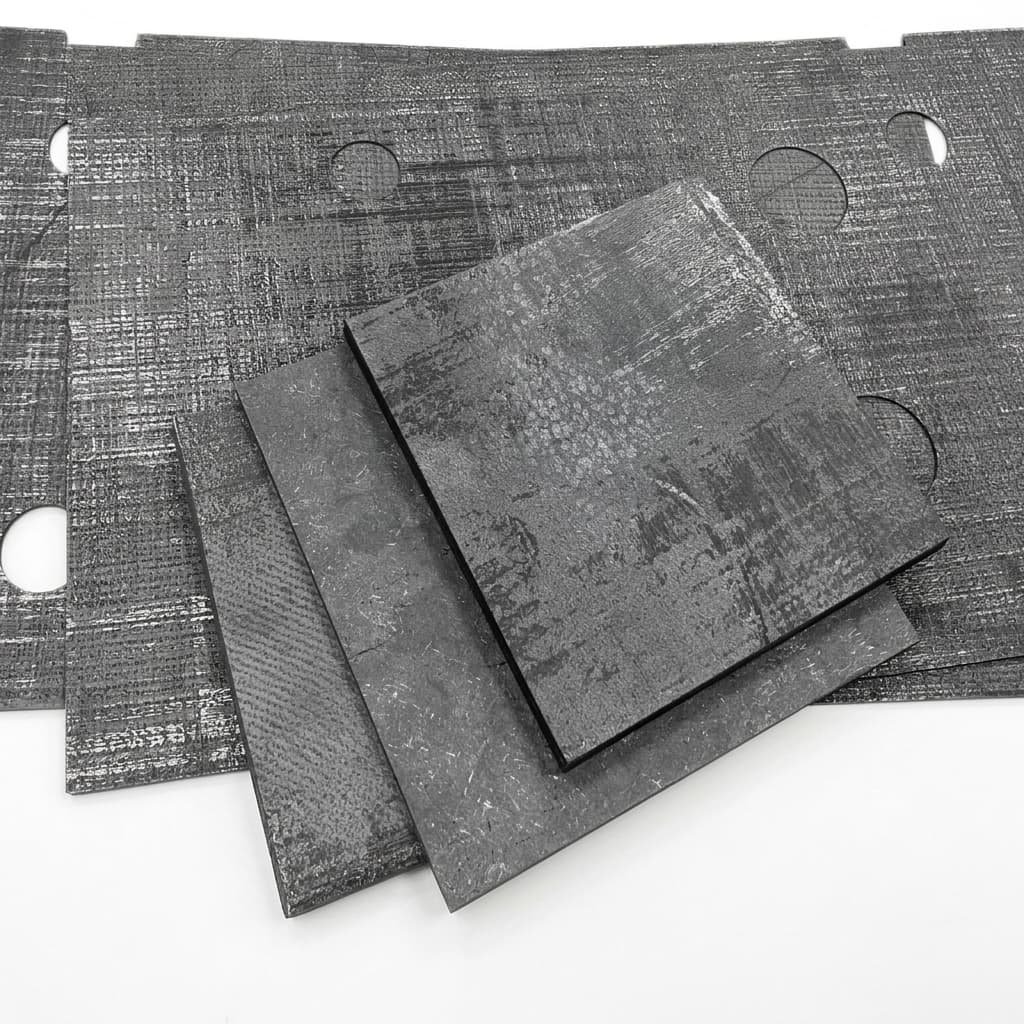
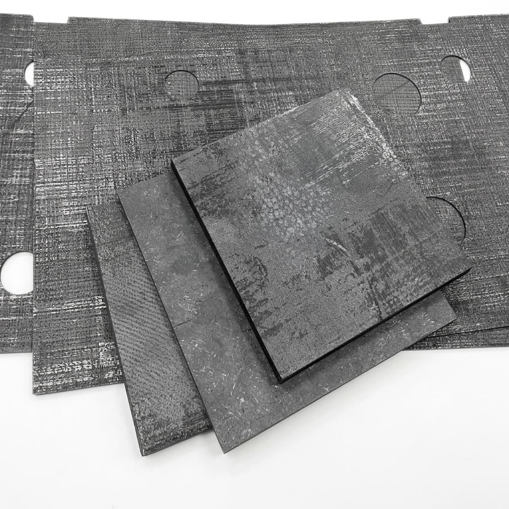
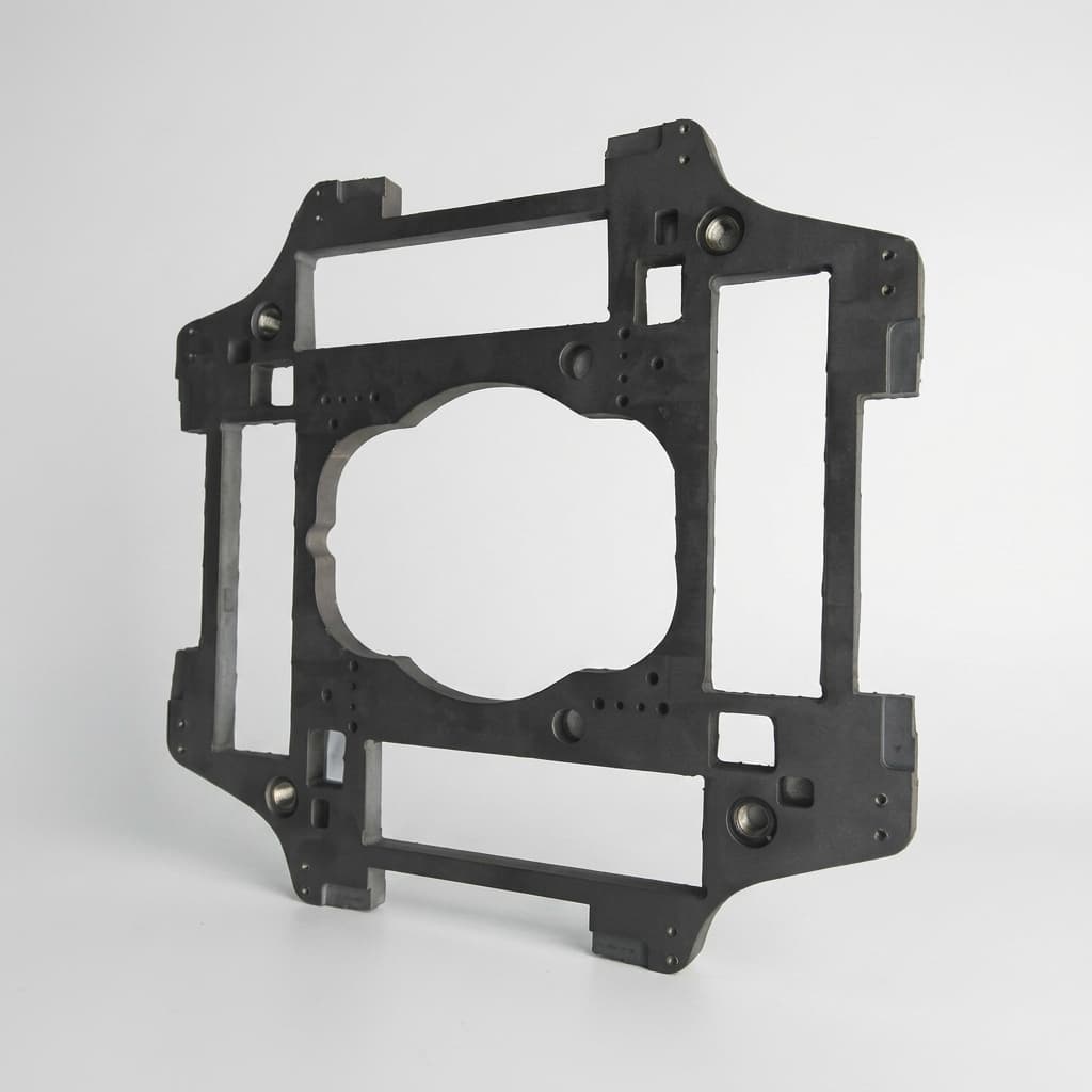
Figure 1: C/C sheets and perforated plates from the product image library. The photograph illustrates material form and fiber texture; it does not establish flatness, strength, or an assembled tray's load rating.
1. Thermomechanical Mechanics: Why Metal and Monolithic Graphite Fixtures Fail
Fixture Thermal Mass and Cycle Time
Heating tooling consumes energy as well as furnace capacity. For preliminary comparison, fixture sensible heat is approximated by:
Mass alone does not establish the fixture's share of electrical consumption: specific heat, hot-zone losses, radiation, loading pattern, and the control recipe also matter. As an illustrative mass comparison, replacing a 120 kg rack with a 25 kg assembly reduces tare mass by . It does not prove the same reduction in energy or cycle time. Measure kWh per accepted batch and time to the same qualified workpiece temperature before claiming savings.
Creep, Handling Damage, and Material Trade-Offs
- Heat-resistant metallic fixtures: Creep and warping depend on alloy, stress, temperature, dwell, and cycling. An alloy name alone cannot predict the number of heats before replacement.
- Molybdenum fixtures: High-temperature capability must be balanced against oxidation exposure, grade condition, recrystallization, and handling brittleness.
- Monolithic graphite: Graphite can offer good thermal shock resistance, but unreinforced parts need attention to brittle fracture, machining details, and handling loads. Gas pressure alone does not predict failure.
- C/C composite: Fiber reinforcement and low thermal expansion can support lighter, dimensionally stable fixtures. Specify directional hot properties and inspect slots, joints, and surfaces; do not interpret creep resistance as immunity to deflection or damage.
SGL's high-temperature furnace brochure, pages 24–25, describes charging-system benefits and hot bending behavior for its materials. These supplier observations are not a lifetime guarantee for other grades or assemblies.
2. Material Performance Matrix: C/C Composite vs. Alternatives
Use this qualitative screening matrix to request comparable evidence. It does not substitute for grade-specific design allowables.
| Selection metric | C/C composite | Heat-resistant metal | Molybdenum / TZM | Monolithic graphite | Buyer verification |
|---|---|---|---|---|---|
| Fixture mass | Can enable thin, light structures | Often heavier for the same envelope | Dense refractory metal | Geometry governs total mass | Weigh complete equivalent assemblies |
| Hot dimensional stability | Strong candidate; directional and load-dependent | Check time-dependent creep | Check grade and temperature | Check brittle failure and deflection | Hot loaded test over the specified dwell |
| Temperature capability | Grade and atmosphere-specific | Alloy and load-specific | Grade and atmosphere-specific | Grade and atmosphere-specific | Separate material limit from assembly rating |
| Thermal shock | Low expansion can be beneficial | Check distortion and fatigue | Check material condition | Grade and geometry matter | Validate the actual quench cycle |
| Carbon contact risk | Requires alloy compatibility review | Check metal-to-metal reactions | Check diffusion and contact reactions | Also presents carbon contact | Qualified barrier and contact coupons |
| Slot / joint behavior | Notches and interlaminar shear matter | Welds and joints need inspection | Handling damage can govern | Brittle edges need protection | Drawing review and inspection criteria |
| Atmosphere limits | Oxidation and process gases require review | Alloy-specific oxidation limits | Protect against oxidation | Protect against oxidation | Define gas purity, dew point, and upset conditions |
| Lifecycle cost | Include barriers, inspection, and spares | Include straightening and replacement | Include handling and replacement | Include breakage and replacement | Compare cost per accepted batch |
For a named-grade reference only, the SIGRABOND Performance datasheet lists typical density 1.5 g/cm³, flexural strength 300 MPa, flexural modulus 80 GPa, interlaminar shear strength 8 MPa, and a 2,000°C maximum application temperature in vacuum or inert gas. It distinguishes standard ash content (1,000 ppm) from purified grade (below 10 ppm). These are typical values, not guaranteed design allowables or Sicgraphite lot data; the sheet does not provide a hot creep allowable for the proposed tray.
3. Engineering Architecture: Modular Egg-Crate Grids vs. Flat Plates
Modular Egg-Crate Grids
Interlocking slats create an open lattice for supporting larger workpieces. The support arrangement and joint design must transfer load without relying on an assumed uniform distribution.
Figure 2: Conceptual cross-section of a multi-tier modular C/C composite charging grid. Shows interlocking slats, gas-flow paths, contact barriers, and corner posts. Concept only: not a dimensional drawing, load rating, or measured flow result.
- Gas circulation: Open cells can reduce fixture blockage, but the loaded parts, flow direction, tier spacing, and furnace fan determine cooling uniformity. Calculate projected open area in the relevant direction and validate the loaded arrangement.
- Expansion and assembly fit: Specify slot clearance, fiber orientation, and retention together. A universal clearance value cannot account for every grade, tolerance stack, and thermal gradient.
- Repairability: Replaceable slats can reduce replacement cost. After damage, inspect adjacent joints and barriers and obtain approval for return to service; replacement alone does not restore a certified load rating.
Perforated Carrier Plates
Small parts may need perforated plates, screens, or qualified separators to avoid falling through grid cells. Choose thickness and hole pattern against support span, local contact loads, gas access, and contamination limits. Reduced-area contact features can limit contact, but cannot by themselves prevent diffusion bonding or carbon transfer.
4. The Eutectic Melting Hazard: Physics and Countermeasures
Why a Binary Eutectic Temperature Is Not a Safe Operating Limit
Carbon transfer at a clean hot contact can change the workpiece's local composition, leading to unwanted carburization, sticking, or liquid formation. Multicomponent steels, nickel alloys, titanium alloys, and brazing fillers require their own compatibility assessment. Time, contact pressure, surface condition, and atmosphere also affect the result.
The Schunk / Solar Atmospheres technical paper, page 2, warns that eutectic melting may occur above 1,050°C depending on the alloy. Treat this as a warning from that source, not a universal reaction onset or a safe limit below it. Solid-state carbon pickup can matter before visible melting. Obtain metallurgical approval for the actual alloy and cycle, including any brazing filler or residual binder.
Barrier Options and Their Qualification
Ipsen's eutectics guide describes coatings, alumina plates, and ceramic fiber cloth as separation options. The following acceptance steps are procurement recommendations; generic ceramic melting points cannot establish a barrier's vacuum service rating.
| Barrier option | Useful role | Qualification question | Maintenance / release check |
|---|---|---|---|
| Ceramic coating on contact faces | Conformal separation | Does the complete coating system remain compatible, adherent, and continuous in this cycle? | Inspect for wear, chips, and exposed carbon before reuse |
| Dense alumina pads or plates | Discrete support surface | Are contact pressure, thermal shock, chemistry, and heat-flow effects acceptable? | Check cracks, seating, and coverage after loading |
| Ceramic composite separators | Tougher replaceable contact layer | Is the named grade qualified for the vacuum, temperature, and load? | Follow grade-specific inspection and retirement limits |
| Ceramic fiber cloth / paper | Conforming consumable separation | Are binder outgassing, particle shedding, and compression acceptable? | Define replacement interval and ensure parts cannot shift onto carbon |
A barrier must cover every possible contact position, including movement during loading and quenching. Agree a representative contact-coupon trial and acceptable carbon pickup, sticking, and surface condition with the process owner. Do not call a coating maintenance-free or specify a fixed cycle life without relevant test records. Metallic screens or pins require their own reaction assessment and are not universal anti-eutectic barriers.
5. Structural Sizing, Span Deflection, and Load Calculations
Beam Bending Formula and Assumptions
For an initial screening calculation, model a slat as a simply supported, unnotched, rectangular beam under a uniformly distributed static load:
- : force per unit length, N/mm; convert mass to force before using it.
- : unsupported span between actual supports, mm.
- : flexural modulus in the load-bearing fiber direction at the design temperature, N/mm²; obtain a suitable value from the supplier.
- and : slat thickness and height, mm; is in mm⁴.
This idealization omits joint compliance, slot section loss, interlaminar shear, concentrated workpiece loads, lateral instability, and transient gas forces. A room-temperature datasheet modulus cannot establish hot assembly performance. With a half-height slot, the local rectangular-section is only one-eighth of the full-height value before considering the intersection's load transfer. The full-height beam result can therefore be optimistic.
Worked Example: Hypothetical RFQ Screening
Assume a 240 kg payload shared equally by eight slats, a 600 mm span, mm, mm, and an assumed directional hot modulus N/mm². The modulus is a scenario input, not a published property or measured result. With m/s²:
If the buyer proposes a 1.5 mm hot-deflection limit, the unnotched result is below that illustrative criterion. It does not approve this geometry or a 240 kg rating. Fixture self-weight, upper tiers, uneven loading, slots, joints, hot strength, creep over the dwell, and handling loads must still be included in a supplier-reviewed model and qualification test.
What the Supplier Must Resolve Before Release
- Agree allowable hot deflection and permanent set from workpiece alignment and loader clearance requirements; there is no universal requirement here.
- Check strength, joint bearing, notch-root stresses, shear, buckling, and safety factors using the actual grade and support drawing.
- Specify rounded slot roots, edge quality, tolerances, and retention from the design review; thickness, root radius, and clearance are not universal catalogue rules.
- Qualify the fully loaded assembly over representative heating, dwell, quench, and handling conditions, with an inspection and retirement plan.
6. Precursor Chemistry and Matrix Densification: CVI vs. LPI
Fiber architecture and matrix processing affect directional properties and machining behavior. Mersen's Aerolor product page distinguishes conventional 2D materials from 2.5D materials with a pyrolytic graphite matrix for demanding applications, including heat-treatment fixtures. It does not establish interchangeable strength or purity values across these architectures.
- 2D woven constructions: Ask for in-plane properties and through-thickness shear data, especially around slots and pins.
- 2.5D reinforced constructions: Ask how through-thickness reinforcement affects delamination resistance and the proposed machining layout; architecture alone does not prove impact immunity.
- Chemical vapor infiltration (CVI): Deposits carbon within the preform from a gas precursor. Request final density, porosity, purification state, and directional test results.
- Liquid impregnation and pyrolysis (LPI / PIP): Builds the matrix through impregnation and carbonization cycles. Evaluate the finished grade rather than assuming a specific cycle count or lower quality from the process name.
Neither route by itself guarantees low ash, oxidation resistance, or a specific service life. Request lot traceability and test conditions for the finished material.
7. Procurement & RFQ Specification Table
Use this matrix to obtain comparable quotations. Values and acceptance methods must be agreed for the application; they are not presented as universal industry standards.
| RFQ parameter | Information to supply | Evidence to request | Release decision |
|---|---|---|---|
| Furnace envelope and supports | Usable volume, rail locations, loader interfaces, clearances | Assembly drawing and interference review | Furnace OEM / operator approves fit |
| Payload and tier layout | Mass per tier, contact positions, upper-tier reactions | Load map, analysis assumptions, rated assembly | All load cases covered |
| Thermal cycle and atmosphere | Peak temperature, dwell, ramps, vacuum / gas conditions, contaminants | Written grade and assembly suitability | Limits match the complete cycle |
| Fiber architecture | Direction of slats, plates, posts, and machined features | Grade identification and directional property data | Load path matches reinforcement |
| Density and porosity | Agreed grade-specific acceptance range | Lot report with method, specimen, and conditioning | Results meet the agreed range |
| Hot strength and deflection | Alignment tolerance, permanent-set limit, duty and service interval | Suitable composite flexure / creep methods, specimen orientation, temperature, atmosphere, and duration | Supplier allowables support the design |
| Purity and cleanliness | Process-specific ash and elemental contamination limits | Separate ash and elemental reports with detection limits | Results meet each named limit |
| Contact barriers | Workpiece alloy, fillers, contact map, allowable surface change | Barrier specification and contact-coupon evidence | Metallurgist approves compatibility |
| Slots, joints, and stacking | Drawing tolerances, root details, retention, tier height | Dimensional report and validated inspection method | Assembly fits without forced joints |
| Inspection and lifecycle | Handling method, wear criteria, spares and repair process | Inspection plan, retirement rules, traceability | Operator can maintain the rated configuration |
Do not apply a monolithic-ceramic flexure method to a C/C laminate without confirming its scope and suitability. Ensure quoted strength values use comparable specimen geometry, fiber orientation, loading mode, and temperature. Low total ash does not prove that every harmful trace element is below detection.
8. The 8-Point Engineering and Procurement Audit Checklist
Before releasing a purchase order or approving a production trial:
- 1. Envelope and interfaces: Confirm hot-zone fit, clearances, rails, loader travel, total assembly mass, and OEM restrictions.
- 2. Contact compatibility: Identify every workpiece alloy and filler; approve barriers for all possible contact positions and the complete cycle.
- 3. Loaded gas flow: Review projected open area, part spacing, tier blockage, and quench direction; define cooling-uniformity acceptance.
- 4. Structural drawing: Review support spans, notches, edge quality, joints, retention, and load orientation against approved analysis.
- 5. Material integrity: Obtain lot and grade records; define visual and, where suitable, validated non-destructive inspection criteria for that porous composite.
- 6. Purity: Agree ash, elemental limits, test methods, sampling, detection limits, cleaning, and packing for the process.
- 7. Stacking and handling: Include upper-tier loads, alignment, lift points, dynamic forces, and approved repair / retirement rules.
- 8. Bakeout and first trial: Agree a supplier- and furnace-approved cleaning / bakeout recipe and acceptance for outgassing, hot deflection, contact condition, and part quality.
Submit your furnace dimensions and payload requirements to Sicgraphite for a custom C/C fixturing review, including the support drawing, alloy, atmosphere, peak temperature, dwell, and quench cycle.
9. Frequently Asked Questions (FAQ)
Q1: Can C/C trays be used with air burn-off or oxygen delubing cycles?
Do not select unprotected C/C for these cycles. Oxidation depends on temperature, oxygen exposure, time, and grade. The Schunk / Solar paper warns about unloading into air above 350°C. Agree cooling and unloading limits with the supplier and furnace operator; a generic oxidation-onset number or unspecified coating is insufficient approval.
Q2: Does a 20-bar gas-quench rating determine the slat thickness?
No. Gas type, temperature, local velocity, flow direction, geometry, support span, and payload determine forces and cooling behavior. Obtain an assembly assessment for the actual furnace. Pressure alone cannot establish a minimum thickness or fixture life.
Q3: How long do ceramic barrier coatings last?
There is no universal cycle count. Loading abrasion, contact pressure, coating continuity, thermal cycling, and process chemistry matter. Agree inspection frequency, rejection criteria, and repair qualification. Inspect exposed contact faces and replace damaged separators before reuse.
Q4: How should a buyer calculate payback when replacing metallic fixtures?
Use incremental installed cost divided by verified net savings per period. Include barriers, qualification, inspection, spares, and downtime. As a hypothetical arithmetic example, an extra 1,000/month in net savings gives 12 months simple payback. If net savings are zero or negative, this model has no positive payback. Validate energy, accepted-batch throughput, and maintenance savings in the same production cycle; do not add overlapping capacity and cycle-time savings twice.
Q5: Can a damaged slat be replaced without scrapping the rack?
Often, if the assembly was designed for modular repair. Use an approved spare with the correct grade, orientation, geometry, and barrier. Inspect neighboring joints and verify assembly condition before returning it to its approved load; replacement alone does not prove restored capacity.
Q6: Do all C/C grades get stronger at elevated temperatures?
No universal percentage increase should be assumed. Some grades show favorable hot strength, but response depends on architecture, processing, direction, atmosphere, and test method. Request suitable hot strength, modulus, and dwell-dependent deformation data rather than extrapolating a room-temperature coupon value.
10. Planning a C/C Fixturing Upgrade
A useful comparison combines assembly mass, hot-load behavior, contact compatibility, maintainability, and cost per accepted batch. Keep the existing fixture as a measured baseline and qualify the proposed replacement with the same workpiece acceptance criteria.
For a drawing-based quotation, review Sicgraphite's C/C composite tray offering and send the support layout and production cycle to the team. Ask the quotation to identify the proposed grade, available hot-property evidence, barrier scope, inspection documents, spares, and any unresolved qualification work.
11. Sources and References
Sources reviewed November 3, 2026. These publications support material selection and risk assessment; none is a Sicgraphite lot certificate, independent endorsement, or approval of the worked example.
- SGL Carbon — SIGRABOND Performance datasheet. One-page sheet marked July 2021, TDS CFRC-U.00. Named-grade typical properties, purified versus standard ash content, and material application temperature; explicitly directs engineering users to the supplier.
- Mersen — Carbon/Carbon Composite Products (Aerolor). Primary manufacturer description of 2D and 2.5D materials and heat-treatment loading-rack applications; not a numerical hot-strength specification.
- Ipsen — Understanding Eutectics: A Guide for Heat-Treating Professionals. Furnace-maker guidance on contact interactions, phase diagrams, ceramic barriers, and coating inspection.
- Warwick, Hill, and Herring — Technical Considerations for the Use of Carbon/Carbon Composite Materials for Fixtures and Grids. December 2013 technical article hosted by Solar Manufacturing. Page 2 discusses alloy-dependent reaction and air-exposure risks. Its furnace trials describe a particular setup and cannot establish universal cycle savings or quench approval.
- SGL Carbon — Specialty Graphites for High-Temperature Furnaces. Pages 24–25 describe SIGRABOND charging systems and hot bending behavior. Manufacturer claims are grade- and application-specific.
Author

More Posts
Evaluating SiC Coated Graphite Quality: How to Prevent Coating Delamination
A comprehensive engineering and procurement guide to identifying, preventing, and sourcing CVD SiC-coated graphite susceptors immune to delamination and pinholes.
Graphite Heating Elements in High-Temperature Vacuum Furnaces: Meander vs. Cage Geometry, Arcing Prevention, and Creep Resistance
Compare graphite heating elements for vacuum furnaces: meander vs. cage, arcing risks, creep, and terminal design. Build your RFQ with an acceptance checklist.
How to Choose High-Purity Isostatic Graphite for Semiconductor Crystal Growth
A buyer's guide to isostatic graphite for SiC PVT and silicon CZ growth. Learn how grain size, bulk density, and ash content affect yield.