
TaC-Coated Guide Rings for 8-Inch SiC PVT Crystal Growth: Thermal Gradient Stabilization, Vapor Parasitic Etching Control, and Drawing Tolerances
Specify TaC-coated guide rings for 8-inch SiC PVT growth. Compare coating risks, drawing tolerances and inspection evidence, then prepare a drawing-based RFQ.
TaC-coated guide rings for 8-inch SiC PVT crystal growth should be selected as part of a qualified hot-zone assembly. A tantalum carbide coating can protect vapor-facing graphite and change the local radiation boundary, but coating chemistry alone does not establish the correct aperture, thermal gradient, or service life. For a 200 mm program, the practical buying decision is whether the supplier can connect the drawing, coating process, inspection evidence, and furnace trial to the same traceable part revision.
This guide helps crystal-growth engineers, thermal-field designers, and procurement teams prepare that decision. It explains vapor parasitic etching control, thermal-gradient stabilization, material trade-offs, and post-coating tolerances. The useful output is a drawing-controlled RFQ and sample-qualification plan, rather than a universal PVT recipe.
Start with Sicgraphite's TaC-coated guide-ring product scope, compare the adjacent TaC-coated graphite crucible, and review the SiC PVT crystal-growth hot-zone solution. If you already have a drawing, request a feasibility review with its revision and operating conditions.
Engineering and procurement decisions at a glance
- Qualify the complete boundary: A guide ring affects vapor access, radiation exchange, assembly clearance, and deposition sites. Evaluate these together.
- Separate evidence from targets: Published studies support investigating TaC in PVT hot zones. They do not certify every 200 mm ring or a fixed number of growth runs.
- Control finished dimensions: State whether ID, OD, flatness, runout, and edge radii apply before or after coating, and identify the measurement datums.
- Request relevant inspection: Link coating thickness, phase analysis, purity, and defect observations to a defined sampling plan and lot.
- Approve through trials: Compare dimensional change, coating condition, and crystal outcomes against an established furnace baseline before releasing production quantities.
Published and editorially reviewed: November 7, 2026. Scope: Global English-language procurement and engineering guidance for graphite-based guide rings in nominal 200 mm SiC PVT systems. Dimensions below are illustrative RFQ examples, not industry acceptance standards. This article contains no first-party lifetime, yield, price, or defect-reduction dataset. It does not qualify a furnace recipe, certify coating integrity, or transfer results from smaller crystals directly to an 8-inch process.
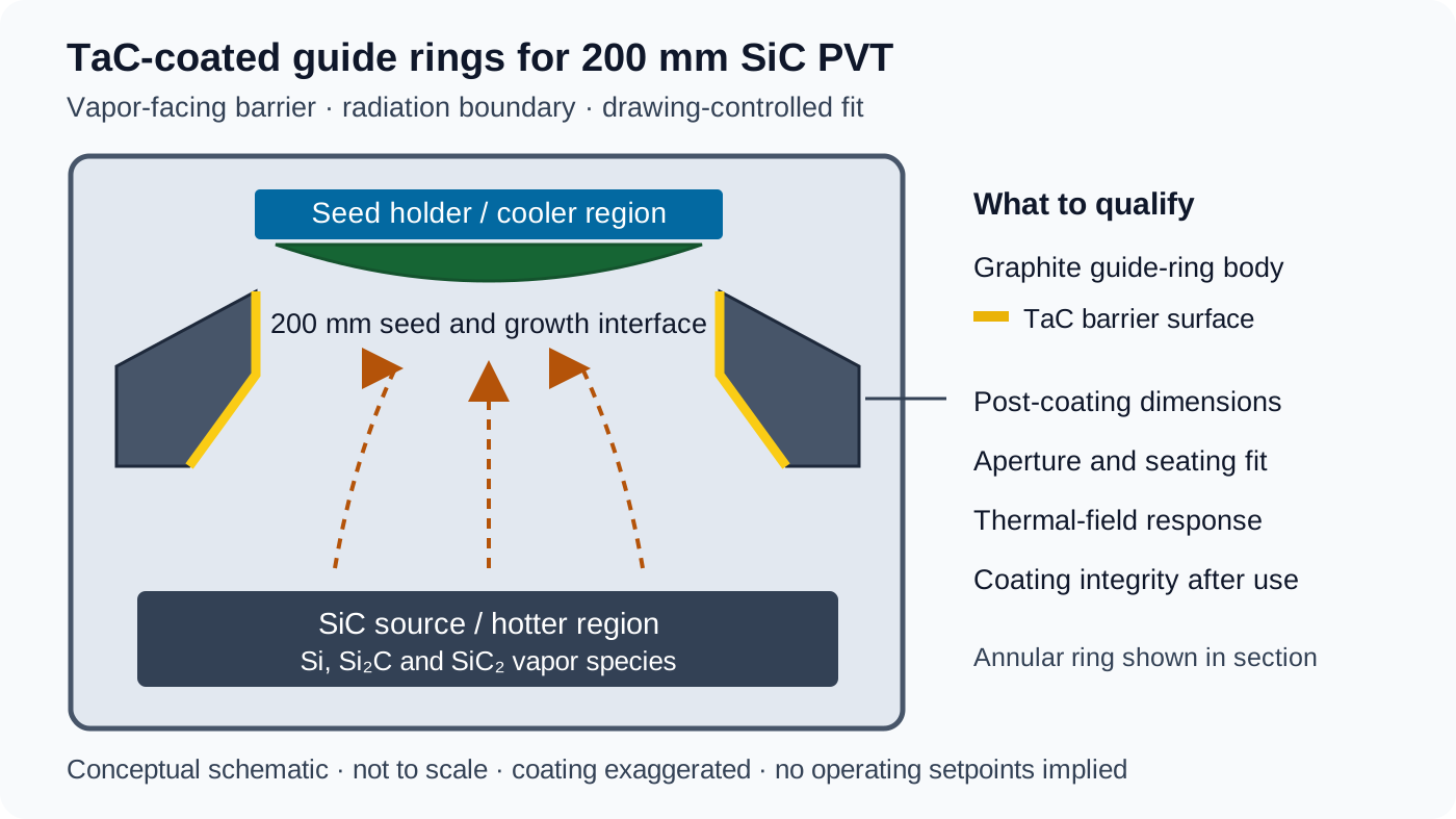
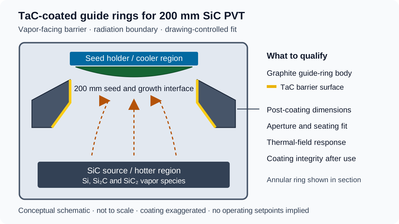
Figure 1: Original explanatory schematic, not to scale. The annular guide ring appears on both sides of the section; its coating is exaggerated for visibility. The drawing shows component relationships, not measured temperatures, validated interface curvature, or a production design.
1. Thermochemical Environment of 8-Inch SiC PVT Sublimation
Physical vapor transport grows SiC by sublimating a hotter source and transporting vapor toward a cooler seed. Relevant gas species include Si, Si₂C, and SiC₂. Their partial pressures and contributions depend on temperature, pressure, source evolution, and the surrounding materials. A list of species is not a balanced decomposition equation, and a single gas-phase Si/C ratio should not be assumed for every furnace.
For the guide ring, the procurement concern is how exposure changes the vapor-facing geometry over a campaign. Reactions with graphite, deposits on cooler regions, and particles released from damaged surfaces can all alter the local boundary. Inspection should distinguish substrate recession from deposited material: a part can gain mass through deposition while also suffering local attack. Net mass change alone is therefore an incomplete erosion metric.
The expression “vapor parasitic etching” in this guide refers to unwanted attack of a hot-zone component rather than useful source sublimation. It should also be distinguished from parasitic SiC nucleation and deposition. These mechanisms can coexist, but preventing one does not establish control of the others. A useful failure report records where the damage occurred, which surfaces were coated, the accumulated hot time, and whether the aperture or seating geometry changed.
A coating cannot compensate for a damaged substrate, an exposed masking boundary, or an unsuitable installation fit. Preserve photographs and dimensional records before use and after a defined trial interval. When crystals show inclusions or edge defects, investigate source preparation, seed attachment, insulation, and handling alongside the ring. Component appearance does not establish a specific dislocation mechanism.
Why SiC-coated graphite needs application-specific review
CVD SiC coatings have established uses in semiconductor equipment, but those operating conditions differ from a PVT sublimation environment. The stability of a SiC coating depends on local vapor equilibrium, temperature, and pressure. A coating suited to an epitaxy susceptor should not be transferred to a hotter source-facing guide ring without evidence. Conversely, a universal failure temperature or “fails within one run” claim is not a sound substitute for testing the actual exposure.
2. What TaC Evidence Supports—and What Still Requires Qualification
Published research gives a reason to evaluate TaC rather than treating it as a guaranteed solution. Fan and colleagues' study of TaC coatings in the SiC PVT process examined coating emissivity and reactivity through modeling and growth experiments. Its abstract reports improvements relevant to thermal uniformity and component protection. This supports considering both thermal and chemical effects when changing a coating; it does not provide a universal emissivity value for a supplied ring.
A separate study of crucible structure using a TaC-coated graphite relay ring considered the ring together with graphite paper around the powder container. Its reported outcomes concern that combined arrangement. They should not be attributed entirely to the coating or advertised as a measured improvement for a different 200 mm furnace.
Earlier research comparing TaC and graphite containers and lids reported differences in parasitic polycrystal nucleation and growth behavior. The purchasing implication is to evaluate the material and its position together. These studies are supporting literature, not Sicgraphite customer case studies or certificates for a production lot.
Phase, composition, and interface control
Ask a coating supplier to identify its deposition route, substrate grade, and evidence for the TaC working surface. X-ray diffraction can identify crystalline phases, but a phase label alone does not establish coating continuity, carbon stoichiometry, adhesion, or purity. Quantitative phase claims need a stated analysis method and detection limit. A witness coupon should be linked to the batch and its position in the coating load; it is not a measurement of every point on the ring.
Carbon-deficient phases, an interlayer, and residual stress deserve review with the supplier. Their presence should be interpreted using the actual process and thermal-cycle evidence. Avoid prescribing an unsupported universal phase percentage or assuming that a particular interlayer guarantees failure. Request representative cross-sections and an agreed definition of unacceptable cracking, exposed graphite, or delamination.
3. Thermal Gradient Stabilization and Vapor Guidance
A guide ring changes the surfaces visible to the seed edge and the path available to vapor. Its thermal effect depends on view factors, surface condition, neighboring components, and heating configuration. Fresh and used surfaces may behave differently. In a thermal model, document the emissivity assumption, whether it is spectral or total, the applicable temperature range, and the sensitivity of the predicted field to that assumption.
For clarity, define the radial temperature difference as:
This is a temperature difference, expressed in kelvin, rather than a gradient in kelvin per unit length. A center-to-edge average gradient also requires the radial distance over which the difference is evaluated. The desired sign and magnitude must come from the furnace's growth-interface and stress objectives. There is no single acceptable crown height or gradient for every 200 mm boule.
A useful scaling check also prevents a common mistake: at equal temperature, emissivity, and view factor, a circular face's radiating area increases by when diameter changes from 150 mm to 200 mm. That is an area ratio, not proof of a 78% increase in peripheral heat loss. Actual net radiation involves the surrounding temperatures and geometry. Do not use the area ratio as a specification for a replacement guide ring.
Similarly, a smaller aperture does not automatically deliver a beneficial high-speed vapor jet. Diffusion, pressure, species reactions, and changing source conditions influence transport. Compare candidate aperture and taper designs with a model appropriate to the process regime, followed by growth trials. Record interface shape, deposits, and any evidence of unwanted bypass paths at the seating interface.
4. Material Selection Matrix for PVT Guide Rings
Use this matrix to frame supplier questions. It is a qualitative screening tool; the entries are not temperature ratings, measured lifetime rankings, or price comparisons. Bare graphite, CVD SiC-coated graphite, and TaC-coated graphite must each be assessed in their intended location.
| Decision factor | Bare graphite | CVD SiC on graphite | TaC on graphite | Evidence to request |
|---|---|---|---|---|
| Vapor-facing surface | Graphite directly exposed | SiC working surface | TaC working surface | Exposure conditions and post-run surface analysis |
| Chemical stability | Local reaction and deposition need review | Sublimation equilibrium needs review | Barrier continuity and reactivity need review | Representative process trial and cross-sections |
| Radiation behavior | Grade and surface dependent | Surface and temperature dependent | Surface and temperature dependent | Optical-property assumptions and model sensitivity |
| Particle risk | Substrate damage can release particles | Deposits or coating damage can release particles | Deposits or coating damage can release particles | Cleanliness record and before/after inspection |
| Dimensional control | Machined geometry is the starting point | Coating changes ID and OD | Coating changes ID and OD | Post-coating dimensional report |
| Thermal cycling | Grade and geometry dependent | Coating/substrate combination matters | Coating/substrate combination matters | Qualified cycle profile and damage criteria |
| Repair route | Depends on remaining sound material | Supplier-specific assessment | Supplier-specific assessment | Disposition criteria and requalification scope |
| Cost per accepted boule | Requires actual life and yield records | Requires actual life and yield records | Requires actual life and yield records | Comparable quotes, replacement rate, and yield data |
A solid TaC ring is a separate design option. Obtain a quotation and mechanical qualification for the required geometry instead of assuming that it costs a fixed multiple or always cracks. For all options, compare purchase, inspection, qualification, replacement, and downtime costs over the same number of accepted boules. A low unit price is insufficient if component variability changes the process baseline.
5. Substrate Selection and Coating Inspection
The graphite substrate and coating should be specified as a combination. Request grade-specific density, grain size, porosity, and thermal-expansion data, including measurement direction and temperature interval. Thermal-expansion compatibility cannot be reduced to one room-temperature number: the coating process, geometry, elastic response, and heating/cooling history also affect residual stress.
If your contamination budget requires low ash or individual elemental limits, put those requirements in the RFQ and define the tested material. A substrate certificate does not automatically certify the deposited coating or the complete finished part. Ask the laboratory to state units, detection limits, sample preparation, and matrix suitability. Nitrogen and other critical species may need a separately agreed method; a generic GDMS report should not be assumed to measure every required contaminant adequately.
Thickness is a qualification variable
Specify a nominal coating thickness and an allowed distribution on identified surfaces. A trial RFQ might propose 40 ± 5 µm, subject to supplier capability and furnace approval. This is an example for the dimensional calculation below, not a universally optimal thickness or a promise of service life. Curved surfaces, recesses, edges, and masking transitions can have different deposition behavior.
Agree how thickness is measured. Destructive cross-sections of representative coupons provide local evidence. Eddy-current or acoustic methods require calibration and validation for the actual coating/substrate geometry before their results can be used for acceptance. No named instrument, visual check, or coupon alone proves that an entire production ring is free of through-coating defects.
For a first article, define the inspected locations and compare the results with the supplied drawing. Preserve an agreed reference for surface condition and edge quality. If the supplier proposes a thermal-cycle or adhesion test, record the procedure, specimen type, and pass/fail criteria. Tests on coupons should be distinguished from tests on a finished ring.
If coating coverage or inspection access is uncertain, send the marked drawing for a coating and metrology review before freezing the purchase specification.
6. Drawing Tolerances and an RFQ Checklist
A 200 mm target crystal diameter does not determine the ring's finished ID, OD, or clearance. Those dimensions depend on the complete hot zone. Identify mounting datums, seating shoulders, vapor-facing surfaces, assembly clearances, and masked regions. State whether dimensions apply before or after CVD, and identify the temperature at which the dimensional report is taken. Room-temperature fit does not establish hot clearance.
Worked example: allowing for coating on an inside diameter
Suppose the required finished ID is 200.00 ± 0.05 mm, and the trial coating specification is 40 ± 5 µm per side. Assume uniform radial deposition for this calculation. The nominal substrate ID is:
If the substrate is machined to 200.08 ± 0.03 mm and each coating surface remains within 0.035–0.045 mm, the simple worst-case finished ID range is 199.96–200.04 mm. The dimensional tolerance contribution is ±0.04 mm, leaving 0.01 mm inside the requested ±0.05 mm band. Measurement uncertainty, nonuniformity, roundness, and the acceptance decision rule still need review; this arithmetic does not approve the part.
For an outside diameter, coating increases the diameter, so the substrate OD must be smaller than the finished nominal OD by twice the nominal thickness. A seating face receives a single thickness contribution in its normal direction. Do not use the diameter allowance for every drawing feature.
Datums, runout, flatness, and edges
Call out circularity and runout separately: runout requires a datum axis, while circularity is a form requirement. Illustrative discussion values such as 0.08 mm runout, 0.04 mm seating flatness, or R0.5–R1.0 mm edge blends must be checked against assembly needs and coating capability. They are not published standards for all 8-inch guide rings.
Ask the supplier to report compliance after coating wherever the drawing specifies a finished feature. Sharp corners and poorly defined edge breaks deserve explicit review because both coating coverage and handling damage matter. Increasing a radius must not silently remove a necessary locating surface or change the effective vapor aperture.
Engineering and procurement verification checklist
Use this checklist to make competing quotations comparable:
- Process scope: State part location, expected temperature/pressure envelope, gas composition, hot time, ramp history, and known failure symptoms.
- Substrate: Identify the graphite grade, property test intervals, contamination requirements, and lot traceability.
- Coating: Identify the deposition route, vapor-facing coverage, masked regions, nominal thickness, variation limits, and coupon sampling locations.
- Drawing: Provide revision-controlled ID, OD, taper, seating dimensions, datums, tolerances, edge treatment, and pre/post-coating status.
- Inspection: Agree dimensional methods, uncertainty, thickness calibration, phase-analysis scope, purity methods, and defect acceptance criteria.
- Qualification: Define the baseline part, trial conditions, inspection intervals, retirement criteria, and required crystal-quality observations.
- Delivery: Agree protective packaging, cleanliness evidence, handling instructions, serial/lot identification, and required inspection documents.
- Change control: Require review of changes to graphite grade, coating route, geometry, masking, cleaning, or inspection method before repeat production.
7. Frequently Asked Questions
Can an existing graphite guide-ring drawing be used unchanged for TaC coating?
Only after reviewing coating allowances, edge geometry, coverage, and assembly clearance. Adding material changes the finished aperture and fits. The coating can also change radiation exchange, so a mechanically fitting ring still needs thermal-field qualification. Preserve the original drawing and issue a controlled revision for the coated trial.
How many PVT runs should a TaC-coated guide ring last?
There is no supported universal count. Define a campaign using hot time, thermal cycles, process conditions, and maintenance history. Establish retirement limits for cracks, exposed graphite, deposits, and dimensional drift. Record service history against those limits. A supplier's result from another furnace is useful context only when its conditions and failure criteria are disclosed.
Does a gold or bronze color mean the coating has failed?
Color alone cannot identify phase composition, remaining thickness, or protective performance. Compare the surface with the incoming reference and inspect for cracks, deposits, and exposed substrate. Use compositional or phase analysis where the disposition depends on chemistry. Do not accept or reject a used ring solely from a photograph or infer that discoloration is always harmless.
How should pinholes and adhesion be assessed?
Agree a method with demonstrated sensitivity for the actual part geometry and materials. Optical inspection can locate visible defects, while calibrated measurements and representative cross-sections add complementary evidence. Coupon results have a sampling boundary. A scratch-test load is not an adhesion strength in MPa, and a leak test requires a defined test boundary; neither should be specified without a suitable procedure.
Can a worn ring be cleaned, stripped, and recoated?
Request a supplier disposition based on substrate integrity, infiltration, remaining dimensions, and contamination history. Cleaning and stripping can alter the part, and requalification may be necessary. Follow the approved supplier and furnace procedures for cleaning, drying, and conditioning; there is no universal acid treatment or high-temperature bake schedule in this guide. Reject repair proposals that cannot account for substrate damage or lot traceability.
8. Procurement Decision Roadmap and RFQ Engagement
First, assemble a baseline dossier: the current drawing, installation position, used-part photographs, measured dimensional changes, and relevant furnace conditions. Identify whether the primary problem is erosion, deposits, coating damage, assembly fit, or crystal-edge behavior. Several symptoms may need separate acceptance criteria.
Second, request a feasibility response before assuming every tolerance and test is available. Ask the supplier to mark deviations, proposed witness-coupon locations, inspection coverage, and any additional tooling or qualification work. Keep proposed targets distinct from confirmed manufacturing capability. Agree which documents accompany prototypes and which are required for repeat lots.
Third, release a limited trial with a defined comparison plan. Hold other process variables as consistent as practicable, document any unavoidable changes, and inspect the used ring as well as the crystal. A favorable single run can justify further evaluation, but does not establish long-term reliability or a causal reduction in defects. Use the accumulated evidence to set production acceptance and retirement limits.
Review Sicgraphite's TaC-coated guide-ring capabilities when preparing the component package. To request a drawing-based RFQ, contact the Sicgraphite team with the drawing revision, quantity, coating boundaries, operating envelope, and requested inspection records. Ask for explicit confirmation of purity limits, metrology scope, feasibility, lead time, and qualification responsibilities in the quotation.
9. Sources and Evidence Boundaries
The following are specific primary research publications. The summaries here use their indexed abstracts; full-text access may require a publisher subscription. Their findings support the material-selection discussion, while the RFQ checklist and worked tolerance calculation are this guide's engineering framework. None establishes Sicgraphite-specific yield, price, lifetime, or a transferable 200 mm process recipe.
- Fan et al., “Impacts of TaC Coating on SiC PVT Process Control and Crystal Quality,” Materials Science Forum 963, 22–25 (2019). Investigates emissivity and reactivity effects using modeling and growth experiments. Supports evaluating chemical and thermal effects together, without supplying a universal ring acceptance specification. Publisher abstract and article record.
- “Control of the growth quality by optimizing the crucible structure for growth of large-sized SiC single crystal,” Journal of Crystal Growth. Examines a TaC-coated relay ring and graphite paper as a combined crucible arrangement. Supports configuration-specific evaluation; results cannot be assigned to coating alone. Publisher abstract and article record.
- Liu et al., “Effects of Source Materials and Container on Growth Process of SiC Crystal,” Crystal Growth & Design 6(9), 2166–2168 (2006). Compares TaC and graphite lids/containers and source combinations. Supports discussion of material-dependent parasitic nucleation and growth behavior. Publisher abstract and article record.
Author

More Posts
Rigid Carbon Felt Insulation for 8-Inch SiC PVT: Rayon vs. Pitch, Outgassing, and Thermal Drift Mitigation
Compare rigid carbon felt insulation for 8-inch SiC PVT: qualify rayon, pitch and PAN grades, outgassing and thermal drift. Build your RFQ evidence checklist.

Graphite Heating Elements in High-Temperature Vacuum Furnaces: Meander vs. Cage Geometry, Arcing Prevention, and Creep Resistance
Compare graphite heating elements for vacuum furnaces: meander vs. cage, arcing risks, creep, and terminal design. Build your RFQ with an acceptance checklist.
CVD SiC Coating vs. Bare Graphite in MOCVD: A Cost & Contamination Analysis
Why bare graphite fails in modern MOCVD. Analyze trace metal contamination, wafer slip, and the lifetime ROI of CVD SiC coated susceptors.